ADVANCED DRIVER ASSISTANCE SYSTEM ADAPTIVE HIGH BEAM SYSTEM U023A87 Lost Communication with Image Processing Module "A"
DESCRIPTION
The headlight ECU sub-assembly LH communicates with the forward recognition camera and millimeter wave radar sensor assembly via CAN communication. If communication between the headlight ECU sub-assembly LH and forward recognition camera stops, the headlight ECU sub-assembly LH will store this DTC.
| DTC No. | Detection Item | DTC Detection Condition | Trouble Area | DTC Output from | Priority |
|---|---|---|---|---|---|
| U023A87 | Lost Communication with Image Processing Module "A" | Detection condition:
The ignition switch is ON. Malfunction status:
A communication malfunction with the forward recognition camera is detected Malfunction duration:
10 seconds or more |
·
Pre-collision system ·
Forward recognition camera ·
Headlight ECU sub-assembly LH |
Headlight Control | B |
| Pattern | DTC output part name
(Display on GTS) |
Suspected Area (Malfunction Status) | ||||
|---|---|---|---|---|---|---|
| Headlight ECU Sub-assembly LH | Forward Recognition Camera | Millimeter Wave Radar Sensor Assembly | ||||
| Headlight Control | Lane Control | Forward Recognition Camera (Front Lighting Control) | Pre-Collision System | Radar Cruise2 | ||
| U023A87 | U023587 | U023587 | U023A87 | U023A87 | ||
|
○: DTC is output -: DTC is not output |
||||||
| Pattern 1 | ○ | ○ | ○ | ○ | ○ | Harness or connector (Open or short) |
| Headlight ECU sub-assembly LH (Internal malfunction) | ||||||
| Forward recognition camera (Internal malfunction) | ||||||
| Millimeter wave radar sensor assembly (Internal malfunction) | ||||||
| Pattern 2 | ○ | - | - | ○ | ○ | Harness or connector (Open) |
| Forward recognition camera (Internal malfunction) | ||||||
| Pattern 3 | ○ | - | - | - | - | Harness or connector (Open) |
| Headlight ECU sub-assembly LH (Internal malfunction) | ||||||
- HINT:
-
If the DTCs are simultaneously output, the inspection area can be narrowed down.
WIRING DIAGRAM
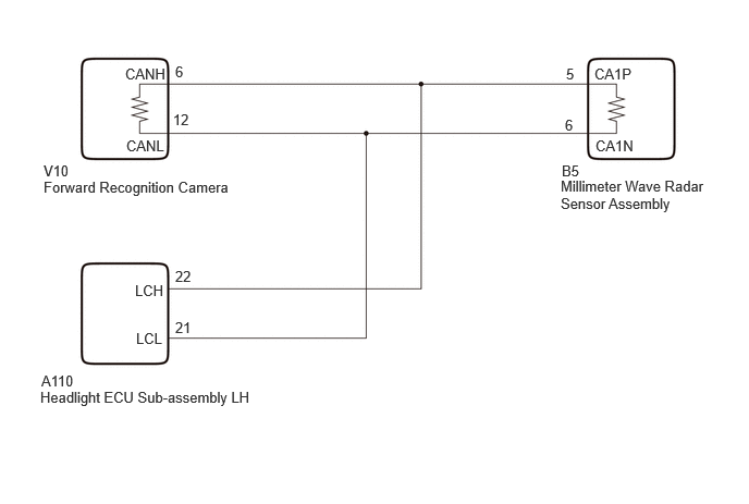
CAUTION / NOTICE / HINT
- NOTICE:
- ·
If the headlight ECU sub-assembly LH has been replaced, it is necessary to synchronize the vehicle information and initialize the headlight ECU sub-assembly LH.
Click hereVehicle Exterior>LIGHTING (EXT)>LIGHTING SYSTEM (w/ Adaptive High Beam System)>INITIALIZATION
·When replacing the headlight ECU sub-assembly LH, always replace it with a new one. If a headlight ECU sub-assembly LH which was installed to another vehicle is used, the information stored in it will not match the information from the vehicle and a DTC may be stored.
·When replacing the forward recognition camera, replace it with a new one. If a forward recognition camera which was installed to another vehicle is used, the information stored in the forward recognition camera will not match the information from the vehicle and a DTC may be stored.
·When the forward recognition camera is replaced with a new one, make sure to perform beam axis adjustment for the forward recognition camera and clear the vehicle control history for each system.
- HINT:
-
Forward recognition camera axis alignment can be performed by using either One Time Recognition, Sequential Recognition or Driving Adjustment.
-
One Time Recognition: Click hereADAS / AD>ADVANCED DRIVER ASSISTANCE SYSTEM>FRONT CAMERA>TARGET ADJUSTMENT(ONE TIME RECOGNITION)
-
Sequential Recognition: Click hereADAS / AD>ADVANCED DRIVER ASSISTANCE SYSTEM>FRONT CAMERA>TARGET ADJUSTMENT(SEQUENTIAL RECOGNITION)
-
Driving Adjustment: Click hereADAS / AD>ADVANCED DRIVER ASSISTANCE SYSTEM>FRONT CAMERA>DRIVING ADJUSTMENT
·When replacing the forward recognition camera, update the ECU security key.
Click hereGeneral>SETUP>WHEN REPLACING OR REMOVING/INSTALLING PARTS>UPDATE ECU SECURITY KEY
PROCEDURE
Check the DTCs and output pattern according to the following table.
- Body Electrical > Headlight Control > Trouble Codes
- 50001 462
- Chassis > Lane Control > Trouble Codes
- 50001 418
- Body Electrical > Pre-Collision System > Trouble Codes
- 50001 432
- Body Electrical > Front Recognition Camera (Front Lighting Control) > Trouble Codes
- 50001 433
- Powertrain > Radar Cruise2 > Trouble Codes
- 50001 426
- Body Electrical > Front Radar Sensor > Trouble Codes
- 50001 429
| Pattern | Display on GTS / Output DTC | ||||
|---|---|---|---|---|---|
| Headlight Control | Lane Control | Pre-Collision System | Forward Recognition Camera (Front Lighting Control) | Radar Cruise2 | |
| Pattern 1 | U023A87 | U023A87 | U023587 | U023A87 | U023587 |
| Pattern 2 | U023A87 | - | - | - | - |
| Pattern 3 | U023A87 | - | - | - | - |
| Pattern 4 | U023A87 | - | - | - | - |
- Result:
Result Proceed to Output in pattern 1 A Output in pattern 2 B Output in pattern 3 C Output in pattern 4 D
A
B
C
D
Pre-procedure1
Disconnect the V10 forward recognition camera connector.
Disconnect the cable from the negative (-) auxiliary battery terminal.
Procedure1
Measure the resistance according to the value(s) in the table below.
- Standard Resistance:
Tester Connection Condition Specified Condition Click Location & Routing(V10)Location & Routingewd_type=routing;type=c;code=V10
Click Connector(V10)Body>No. 1 Roof Wire>Forward Recognition Cameraewd_type=component;type=c;code=V10;pinno=6,12
V10-6 (CANH) - V10-12 (CANL) Cable disconnected from negative (-) auxiliary battery terminal 108 to 132 Ω
- Result:
Proceed to OK NG
Post-procedure1
None
OK
NG