CLUTCH CLUTCH MASTER CYLINDER(for RHD) INSTALLATION
PROCEDURE

 31453
1.INSTALL CLUTCH MASTER CYLINDER PUSH ROD CLEVIS
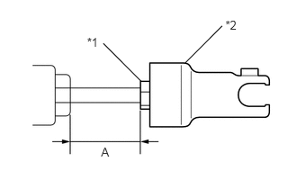
Install the lock nut to the push rod.
| *1 | Lock Nut |
| *2 | Clutch Master Cylinder Push Rod Clevis |
Install the clutch master cylinder push rod clevis to the push rod.
Tighten the lock nut and check the dimension A is same as the dimension A that has been measured.
- Torque:
- 12 N*m (120 kgf*cm, 9 ft.*lbf)
31410
2.INSTALL CLUTCH MASTER CYLINDER ASSEMBLY
Install the clutch master cylinder assembly with the 2 nuts.
- Torque:
- 9.0 N*m (92 kgf*cm, 80 in.*lbf)
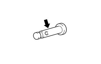
Apply MP grease to the clevis pin.

|
MP grease |
Install the clutch master cylinder push rod clevis to the clutch pedal sub-assembly with the clevis pin and a new clip.
- HINT:
-
Install the clevis pin from the right side of the vehicle.
31481
3.CONNECT CLUTCH MASTER CYLINDER TO FLEXIBLE HOSE TUBE
Using a union nut wrench (10 mm), connect the clutch master cylinder to flexible hose tube to the clutch master cylinder assembly.
- Torque:
- 15 N*m (155 kgf*cm, 11 ft.*lbf)
- NOTICE:
-
Use the formula to calculate special torque values for situations where a union nut wrench is combined with a torque wrench (See page General>INTRODUCTION>REPAIR INSTRUCTION>PRECAUTION).
31434
4.CONNECT CLUTCH RESERVOIR TUBE
Connect the clutch reservoir tube to the clutch master cylinder assembly with the clip.
5.FILL RESERVOIR WITH BRAKE FLUID
6.BLEED CLUTCH LINE
7.INSPECT FOR BRAKE FLUID LEAK
8.INSPECT BRAKE FLUID LEVEL
9.INSPECT AND ADJUST CLUTCH PEDAL
55711
10.INSTALL OUTER COWL TOP PANEL
55722C
11.INSTALL INNER COWL TOP TO COWL BRACE
55815E
12.INSTALL FRONT NO. 1 VENTILATOR SEAL
55735D
13.INSTALL FRONT AIR SHUTTER SEAL RH
14.INSTALL WINDSHIELD WIPER MOTOR AND LINK ASSEMBLY
- HINT:
-
Use the same procedure as for LHD models (See page Vehicle Exterior>WIPER / WASHER>FRONT WIPER MOTOR>INSTALLATION).
55432B
15.INSTALL LOWER INSTRUMENT PANEL FINISH PANEL (w/o Knee Airbag)
73900
16.INSTALL LOWER NO. 1 INSTRUMENT PANEL AIRBAG ASSEMBLY (w/ Knee Airbag)
- HINT:
-
Use the same procedure as for LHD models (See page Vehicle Interior>SUPPLEMENTAL RESTRAINT SYSTEMS>KNEE AIRBAG ASSEMBLY>INSTALLATION).
55606
17.INSTALL NO. 1 INSTRUMENT PANEL UNDER COVER SUB-ASSEMBLY (w/o Knee Airbag)
- HINT:
-
Use the same procedure as for LHD models (See page Vehicle Interior>INTERIOR PANELS / TRIM>LOWER INSTRUMENT PANEL>INSTALLATION).