BRAKE CONTROL / DYNAMIC CONTROL SYSTEMS VEHICLE STABILITY CONTROL SYSTEM(for Built-in Type Yaw Rate Sensor) C1422 Master Cylinder Pressure Sensor Zero Point High Malfunction
DESCRIPTION
The master cylinder pressure sensor is connected to the skid control ECU.
| DTC No. | DTC Detection Condition | Trouble Area |
|---|---|---|
| C1422 | When the stop light switch is OFF, the PMC terminal voltage is more than 0.86 V for 5 seconds or more. | ·
Stop light switch ·
Stop light switch circuit ·
Master cylinder pressure sensor circuit ·
Brake actuator assembly (Master cylinder pressure sensor) |
WIRING DIAGRAM
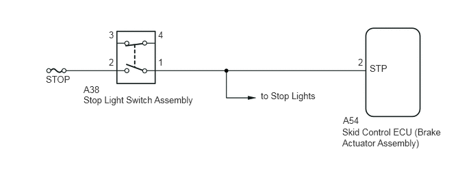
CAUTION / NOTICE / HINT
- NOTICE:
- ·
When replacing the brake actuator assembly, perform zero point calibration (See page Brake>BRAKE CONTROL / DYNAMIC CONTROL SYSTEMS>VEHICLE STABILITY CONTROL SYSTEM(for Built-in Type Yaw Rate Sensor)>CALIBRATION).
·Inspect the fuses for circuits related to this system before performing the following inspection procedure.
- HINT:
-
When C1425 is output together with C1422, inspect and repair the trouble areas indicated by C1425 first (See page Brake>BRAKE CONTROL / DYNAMIC CONTROL SYSTEMS>VEHICLE STABILITY CONTROL SYSTEM(for Built-in Type Yaw Rate Sensor)>C1425).
PROCEDURE
Check the DTC C1425 is output (See page Brake>BRAKE CONTROL / DYNAMIC CONTROL SYSTEMS>VEHICLE STABILITY CONTROL SYSTEM(for Built-in Type Yaw Rate Sensor)>DTC CHECK / CLEAR).
| Result | Proceed to |
|---|---|
| DTC C1425 is not output | A |
| DTC C1425 is output | B |
A
B
Connect the intelligent tester to the DLC3.
Turn the ignition switch to ON.
Turn the tester on.
Enter the following menu: Chassis / ABS/VSC/TRC / Data List.
In accordance with the display on the tester, read the Data List.
| Tester Display | Measurement Item/Range | Normal Condition | Diagnostic Note |
|---|---|---|---|
| Stop Light SW | Stop light switch/OFF or ON | OFF: Brake pedal released
ON: Brake pedal depressed |
- |
| Master Cylinder Sensor | Master cylinder pressure sensor reading/Min.: 0 V, Max.: 5 V | 0.3 to 0.9 V: When brake pedal is released | Reading increases when brake pedal is depressed. |
- Standard Voltage:
Master cylinder pressure sensor reading is 0.86 V or less at the instant the stop light switch changes from off to on.
OK
NG
Start the engine.
Drive the vehicle at a speed of 40 km/h (25 mph) or more and perform braking test (decelerate the vehicle by depressing the brake pedal).
Check if the same DTC is recorded (See page Brake>BRAKE CONTROL / DYNAMIC CONTROL SYSTEMS>VEHICLE STABILITY CONTROL SYSTEM(for Built-in Type Yaw Rate Sensor)>DTC CHECK / CLEAR).
| Result | Proceed to |
|---|---|
| DTC C1422 is not output | A |
| DTC C1422 is output | B |
A
B
Turn the ignition switch off.
Check the brake pedal height and stop light switch installation. (See page Vehicle Exterior>LIGHTING (EXT)>STOP LIGHT SWITCH>INSTALLATION)
- OK:
The brake pedal height and stop light switch installation are normal.
OK
NG
Remove the stop light switch assembly (See page Vehicle Exterior>LIGHTING (EXT)>STOP LIGHT SWITCH>REMOVAL).
Inspect the stop light switch assembly (See page Vehicle Exterior>LIGHTING (EXT)>STOP LIGHT SWITCH>INSPECTION).
OK
NG
Disconnect the skid control ECU connector.
Measure the resistance according to the value(s) in the table below.
- Standard Resistance:
Tester Connection Condition Specified Condition A54-2 (STP) - A38-1 Always Below 1 Ω
OK
NG