BRAKE SYSTEM (OTHER) BRAKE PEDAL REMOVAL
PROCEDURE

 83100
1.REMOVE COMBINATION METER ASSEMBLY
55606
2.REMOVE NO. 1 INSTRUMENT PANEL UNDER COVER SUB-ASSEMBLY
55433B
3.REMOVE LOWER NO. 2 INSTRUMENT PANEL FINISH PANEL (for LHD)
55432B
4.REMOVE LOWER INSTRUMENT PANEL FINISH PANEL (w/o Knee Airbag)
73900
5.REMOVE LOWER NO. 1 INSTRUMENT PANEL AIRBAG ASSEMBLY (w/ Knee Airbag)
84340
6.REMOVE STOP LIGHT SWITCH ASSEMBLY
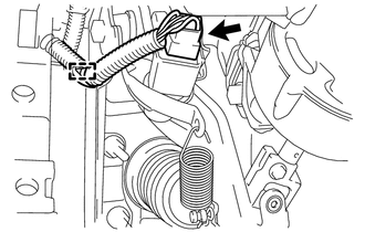
Disconnect the connector from the stop light switch assembly.
Disengage the harness clamp from the pedal support.
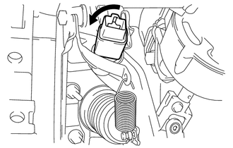
Turn the stop light switch counterclockwise and remove the stop light switch assembly.
47264D
7.SEPARATE BRAKE MASTER CYLINDER PUSH ROD CLEVIS
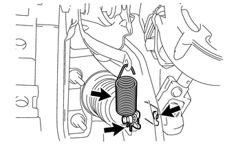
Remove the brake pedal return spring.
Remove the clip and push rod pin and separate the push rod clevis from the brake pedal.
45260
8.SEPARATE NO. 2 STEERING INTERMEDIATE SHAFT ASSEMBLY (for LHD)
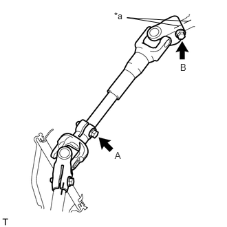
Place matchmarks on the No. 2 steering intermediate shaft assembly and steering column assembly.
| *a | Matchmark |
Loosen bolt A.
Remove bolt B and separate the No. 2 steering intermediate shaft assembly from the steering column assembly.
55106
9.REMOVE BRAKE PEDAL SUPPORT SUB-ASSEMBLY (for LHD)
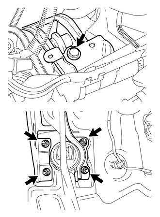
Remove the 4 nuts, bolt and the pedal support.
55106
10.REMOVE BRAKE PEDAL SUPPORT SUB-ASSEMBLY (for RHD)
Remove the wire harness clamp.
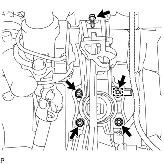
Remove the 4 nuts, bolt and the pedal support.