INTERIOR PANELS / TRIM LOWER INSTRUMENT PANEL REMOVAL
CAUTION / NOTICE / HINT
- HINT:
-
All bolts, screws and nuts relevant to installing and removing the instrument panel are shown, along with their alphabetic codes, in the table below.
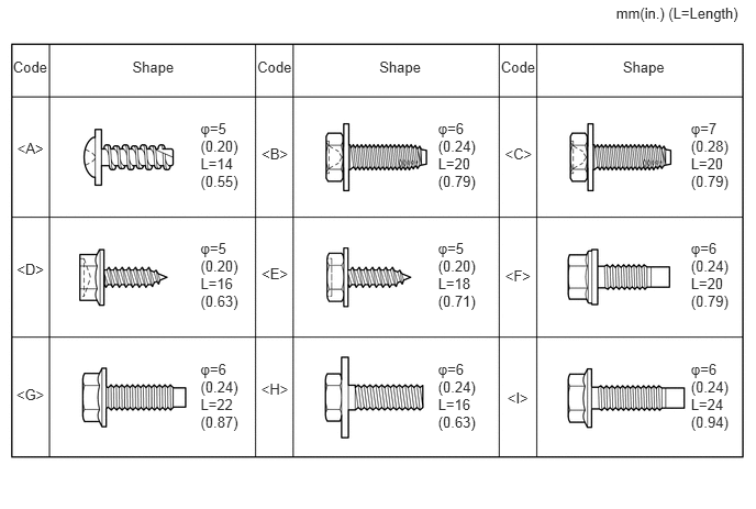 5.84,0.046 7.070,0.239 1.230,0.193 10 mm(in.) (L=Length) 1.901,1.135 2.353,1.800 0.452,0.665 10 φ=5 (0.20) L=14 (0.55) 0.122,0.554 0.476,0.716 0.355,0.162 10 Code 1.255,0.553 1.683,0.717 0.428,0.164 10 Shape 0.163,1.327 0.436,1.476 0.273,0.148 10 <A> 2.48,1.375 2.753,1.523 0.273,0.148 10 <B> 4.786,1.38 5.066,1.529 0.280,0.148 10 <C> 0.159,2.465 0.440,2.614 0.281,0.148 10 <D> 2.48,2.508 2.753,2.656 0.273,0.148 10 <E> 4.789,2.53 5.062,2.678 0.273,0.148 10 <F> 0.155,3.652 0.443,3.800 0.288,0.148 10 <G> 2.476,3.604 2.757,3.752 0.281,0.148 10 <H> 2.439,0.554 2.793,0.716 0.355,0.162 10 Code 3.596,0.553 4.024,0.717 0.428,0.164 10 Shape 4.748,0.554 5.103,0.716 0.355,0.162 10 Code 5.905,0.553 6.334,0.717 0.428,0.164 10 Shape 4.153,2.269 4.605,2.935 0.452,0.665 10 φ=5 (0.20) L=18 (0.71) 1.901,2.269 2.353,2.935 0.452,0.665 10 φ=5 (0.20) L=16 (0.63) 4.153,1.135 4.605,1.800 0.452,0.665 10 φ=6 (0.24) L=20 (0.79) 6.55,2.269 7.002,2.935 0.452,0.665 10 φ=6 (0.24) L=20 (0.79) 1.901,3.414 2.353,4.079 0.452,0.665 10 φ=6 (0.24) L=22 (0.87) 4.153,3.414 4.605,4.079 0.452,0.665 10 φ=6 (0.24) L=16 (0.63) 6.55,1.135 7.002,1.800 0.452,0.665 10 φ=7 (0.28) L=20 (0.79) 6.55,3.414 7.002,4.079 0.452,0.665 10 φ=6 (0.24) L=24 (0.94) 4.81,3.686 5.042,3.834 0.233,0.148 10 <I>
PROCEDURE

 55302A
1.REMOVE UPPER INSTRUMENT PANEL SUB-ASSEMBLY
55550
2.REMOVE GLOVE COMPARTMENT DOOR ASSEMBLY
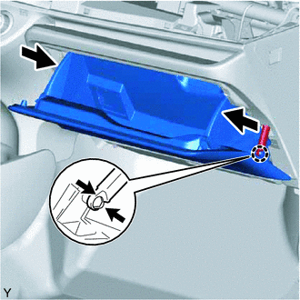
Disengage the claw and separate the glove compartment door stoppers from the glove compartment door.
Slightly flex the upper part of the glove compartment door to release the 2 stoppers and open the glove compartment door until it is horizontal.
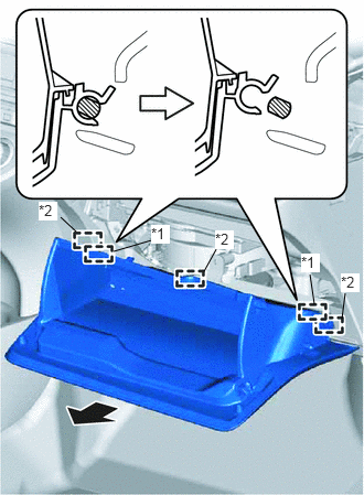
Pull the glove compartment door out horizontally to disengage the 2 hinges and 3 guides and remove the glove compartment door.
| *1 | Hinge |
| *2 | Guide |
- NOTICE:
-
Pull the glove compartment door out horizontally. Otherwise, the hinge may be damaged, making re-installation impossible.
55607
3.REMOVE NO. 2 INSTRUMENT PANEL UNDER COVER SUB-ASSEMBLY
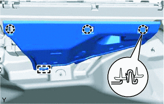
Disengage the 3 claws and the guide and remove the instrument panel under cover.
55606
4.REMOVE NO. 1 INSTRUMENT PANEL UNDER COVER SUB-ASSEMBLY
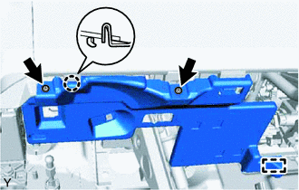
Remove the 2 <A> screws.
Disengage the claw and the guide and remove the instrument panel under cover.
55433B
5.REMOVE LOWER NO. 2 INSTRUMENT PANEL FINISH PANEL (for LHD)
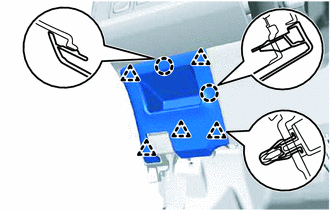
Disengage the 5 clips and the 2 claws and remove the instrument panel finish panel.
55432B
6.REMOVE LOWER INSTRUMENT PANEL FINISH PANEL (w/o Knee Airbag)
for LHD:
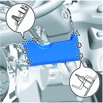
Disengage the 2 clips and the 5 claws and remove the instrument panel finish panel.
for RHD:
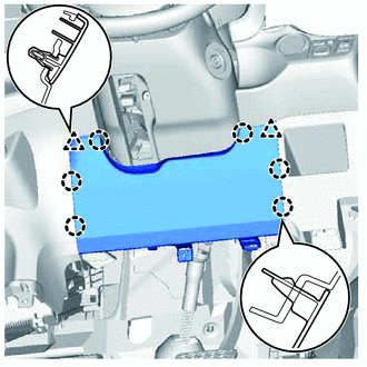
Disengage the 2 clips and the 6 claws and remove the instrument panel finish panel.
73900
7.REMOVE LOWER NO. 1 INSTRUMENT PANEL AIRBAG ASSEMBLY (w/ Knee Airbag)
55521C
8.REMOVE STEREO OPENING COVER WITH BRACKET (w/o Radio Receiver)
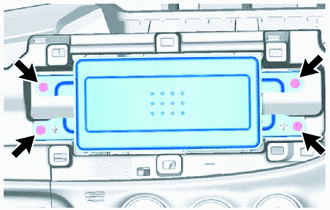
Remove the 4 screws and the stereo opening cover with bracket.
9.REMOVE RADIO RECEIVER ASSEMBLY WITH BRACKET (w/ Radio Receiver)
55900
10.REMOVE AIR CONDITIONING CONTROL ASSEMBLY (for Automatic Air Conditioning System)
11.SEPARATE AIR CONDITIONING PANEL ASSEMBLY (for Manual Air Conditioning System)
55906A
12.DISCONNECT DEFROSTER DAMPER CONTROL CABLE SUB-ASSEMBLY (for Manual Air Conditioning System)
55908A
13.DISCONNECT AIR INLET DAMPER CONTROL CABLE SUB-ASSEMBLY (for Manual Air Conditioning System)
55909A
14.DISCONNECT AIR MIX DAMPER CONTROL CABLE SUB-ASSEMBLY (for Manual Air Conditioning System)
58910C
15.REMOVE REAR CONSOLE BOX ASSEMBLY
53601
16.SEPARATE HOOD LOCK CONTROL LEVER SUB-ASSEMBLY
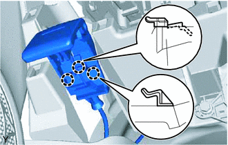
Disengage the 3 claws and separate the hood lock control lever.
55303B
17.REMOVE LOWER INSTRUMENT PANEL SUB-ASSEMBLY
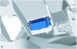
Disengage the 2 claws and disconnect the DLC3 connector.
Disconnect the clamps and connectors.
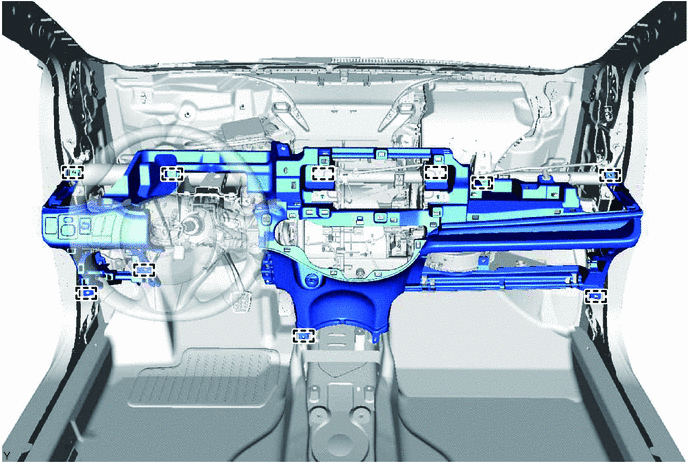
Remove the 6 <B> or <C> bolts, <D> or <E> screw, 2 <F> or <H> or <I> bolts, and bolt from the lower instrument panel.
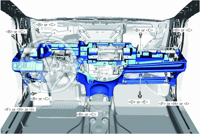
Disengage the 10 guides and remove the lower instrument panel.