NAVIGATION / MULTI INFO DISPLAY NAVIGATION SYSTEM Speaker Circuit
DESCRIPTION
The navigation receiver assembly sends sound signals to the speakers.
WIRING DIAGRAM
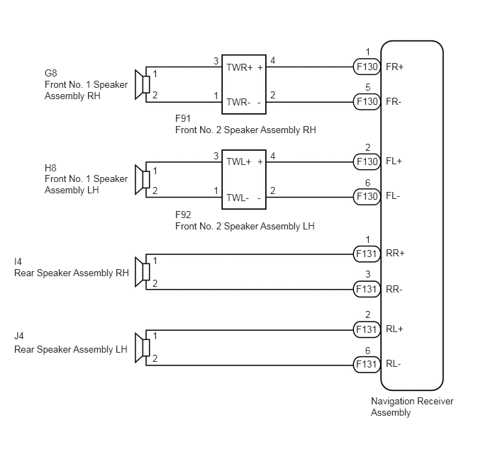
CAUTION / NOTICE / HINT
- NOTICE:
-
Check that the wire harness is properly installed and does not have any sharp bends, pinching or loose connections (See page General>INTRODUCTION>HOW TO TROUBLESHOOT ECU CONTROLLED SYSTEMS>ELECTRONIC CIRCUIT INSPECTION PROCEDURE).
PROCEDURE
Disconnect the F130 and F131 navigation receiver assembly connectors.
Disconnect the G8 and H8 front No. 1 speaker assembly connectors.
Disconnect the F91 and F92 front No. 2 speaker assembly connectors.
Disconnect the I4 and J4 rear speaker assembly connectors.
Measure the resistance between each of the navigation receiver assembly and the front No. 2 speaker assembly to check for an open circuit in the wire harness.
- Standard Resistance:
Tester Connection Condition Specified Condition F130-1 (FR+) - F91-4 (+) Always Below 1 Ω F130-5 (FR-) - F91-2 (-) Always Below 1 Ω F130-2 (FL+) - F92-4 (+) Always Below 1 Ω F130-6 (FL-) - F92-2 (-) Always Below 1 Ω
Measure the resistance between each of the front No. 2 speaker assembly and front No. 1 speaker assembly to check for an open circuit in the wire harness.
- Standard Resistance:
Tester Connection Condition Specified Condition F91-3 (TWR+) - G8-1 Always Below 1 Ω F91-1 (TWR-) - G8-2 Always Below 1 Ω F92-3 (TWL+) - H8-1 Always Below 1 Ω F92-1 (TWL-) - H8-2 Always Below 1 Ω
Measure the resistance between each of the navigation receiver assembly and the rear speaker assembly to check for an open circuit in the wire harness.
- Standard Resistance:
Tester Connection Condition Specified Condition F131-1 (RR+) - I4-1 Always Below 1 Ω F131-3 (RR-) - I4-2 Always Below 1 Ω F131-2 (RL+) - J4-1 Always Below 1 Ω F131-6 (RL-) - J4-2 Always Below 1 Ω
Measure the resistance between each speaker assembly and body ground to check for a short circuit in the wire harness.
- Standard Resistance:
Tester Connection Condition Specified Condition G8-1 - Body ground Always 10 kΩ or higher G8-2 - Body ground Always 10 kΩ or higher H8-1 - Body ground Always 10 kΩ or higher H8-2 - Body ground Always 10 kΩ or higher F91-4 (+) - Body ground Always 10 kΩ or higher F91-2 (-) - Body ground Always 10 kΩ or higher F92-4 (+) - Body ground Always 10 kΩ or higher F92-2 (-) - Body ground Always 10 kΩ or higher I4-1 - Body ground Always 10 kΩ or higher I4-2 - Body ground Always 10 kΩ or higher J4-1 - Body ground Always 10 kΩ or higher J4-2 - Body ground Always 10 kΩ or higher
OK
NG
Remove the front No. 1 speaker assembly (See page Audio / Visual / Telematics>AUDIO / VIDEO>FRONT DOOR SPEAKER>REMOVAL).
Inspect the front No. 1 speaker assembly (See page Audio / Visual / Telematics>AUDIO / VIDEO>FRONT DOOR SPEAKER>INSPECTION).
OK
NG
Remove the rear speaker assembly (See page Audio / Visual / Telematics>AUDIO / VIDEO>REAR DOOR SPEAKER>REMOVAL).
Inspect the rear speaker assembly (See page Audio / Visual / Telematics>AUDIO / VIDEO>REAR DOOR SPEAKER>INSPECTION).
OK
NG
Replace the front No. 2 speaker assembly with a known good one (See page Audio / Visual / Telematics>AUDIO / VIDEO>PILLAR SPEAKER>REMOVAL).
Check that the malfunction disappears.
- NOTICE:
- ·
Connect all the connectors that were disconnected to the front No. 2 speaker assemblies.
·Perform the above inspection on both LH and RH sides.
- OK:
Malfunction disappears.
OK
NG