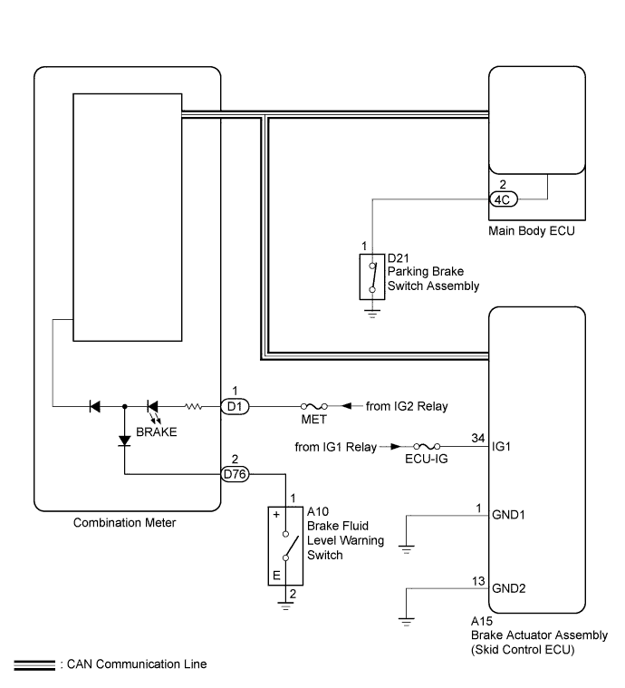
ANTI-LOCK BRAKE SYSTEM (for Sedan) > Brake Warning Light Remains ON |
| 1.PREPARE FOR INSPECTION |
Check that both of the following conditions are satisfied.
| NEXT | |
 |
| 2.CHECK IF SKID CONTROL ECU CONNECTOR IS SECURELY CONNECTED |
Check if the brake actuator assembly (skid control ECU) connector is securely connected.
|
| ||||
| OK | |
|
| 3.CHECK CAN COMMUNICATION SYSTEM |
Check if CAN communication system DTCs are output (Click here).
| Result | Proceed to |
| DTC is not output | A |
| DTC is output | B |
|
| ||||
| A | |
|
| 4.PERFORM ACTIVE TEST USING TECHSTREAM (Indicat. Lamp Brake) |
Turn the ignition switch off.
Connect the Techstream to the DLC3.
Turn the ignition switch to ON.
Turn the Techstream on.
Enter the following menus: Body Electrical / Combination Meter / Active Test.
According to the display on the Techstream, perform the Active Test.
| Tester Display | Test Part | Control Range | Diagnostic Note |
| Indicat. Lamp Brake | Brake warning light | OFF/ON | Perform the test with the vehicle stopped and the engine idling |
Check that the brake warning light on the combination meter turns on or off in accordance with the tester operation.
|
| ||||
| OK | |
|
| 5.READ VALUE USING TECHSTREAM (PARKING BRAKE SWITCH) |
Turn the ignition switch off.
Connect the Techstream to the DLC3.
Turn the ignition switch to ON.
Turn the Techstream on.
Enter the following menus: Chassis / ABS/VSC/TRAC / Data List.
According to the display on the Techstream, read the Data List.
| Tester Display | Measurement Item/Range | Normal Condition | Diagnostic Note |
| Parking Brake SW | Parking brake switch / ON or OFF | ON: Parking brake applied OFF: Parking brake released | - |
Using the tester, check the input of the switch operation when the parking brake pedal is operated.
|
| ||||
| OK | |
|
| 6.INSPECT BRAKE FLUID LEVEL WARNING SWITCH |
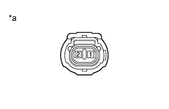 |
Turn the ignition switch off.
Remove the reservoir filler cap and strainer.
Disconnect the brake fluid level warning switch connector.
Measure the resistance according to the value(s) in the table below.
| Tester Connection | Switch Condition | Specified Condition |
| 1 - 2 | Switch OFF (Float up) | 10 kΩ or higher |
| 1 - 2 | Switch ON (Float down) | Below 1 Ω |
| *a | Component without harness connected (Brake Fluid Level Warning Switch) |
Reconnect the brake fluid level warning switch connector.
Reinstall the reservoir filler cap and strainer.
|
| ||||
| OK | |
|
| 7.CHECK HARNESS AND CONNECTOR (IG1 TERMINAL) |
Turn the ignition switch off.
Make sure that there is no looseness at the locking part and the connecting part of the connectors.
Disconnect the A15 brake actuator assembly (skid control ECU) connector.
Check the connector case and terminals for deformation and corrosion.
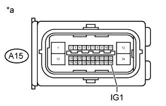 |
Measure the voltage according to the value(s) in the table below.
| Tester Connection | Switch Condition | Specified Condition |
| A15-34 (IG1) - Body ground | Ignition switch ON | 11 to 14 V |
| *a | Front view of wire harness connector (to Brake Actuator Assembly (Skid Control ECU)) |
|
| ||||
| OK | |
|
| 8.CHECK HARNESS AND CONNECTOR (GND1 TERMINAL) |
Turn the ignition switch off.
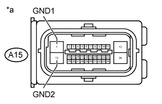 |
Measure the resistance according to the value(s) in the table below.
| Tester Connection | Condition | Specified Condition |
| A15-1 (GND1) - Body ground | Always | Below 1 Ω |
| A15-13 (GND2) - Body ground | Always | Below 1 Ω |
| *a | Front view of wire harness connector (to Brake Actuator Assembly (Skid Control ECU)) |
Reconnect the A15 brake actuator assembly (skid control ECU) connector.
|
| ||||
| OK | |
|
| 9.CHECK HARNESS AND CONNECTOR (COMBINATION METER - BRAKE FLUID LEVEL WARNING SWITCH) |
Disconnect the D76 combination meter assembly connector and the A10 brake fluid level warning switch.
Measure the resistance according to the value(s) in the table below.
| Tester Connection | Condition | Specified Condition |
| D76-2 (SW) - A10-1 (+) | Always | Below 1 Ω |
| A10-2 (E) - Body ground | Always | Below 1 Ω |
| D76-2 (SW) - Body ground | Always | 10 kΩ or higher |
Reconnect the D76 combination meter assembly connector and the A10 brake fluid level warning switch.
|
| ||||
| OK | ||
 | ||
| ||
| 10.INSPECT PARKING BRAKE SWITCH ASSEMBLY |
Disconnect the D21 parking brake switch assembly connector.
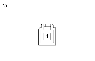 |
Measure the resistance according the value(s) in the table below.
| Tester Connection | Switch Condition | Specified Condition |
| 1 - Body ground | Parking brake applied (Switch pin not pushed in) | Below 1 Ω |
| Parking brake released (Switch pin pushed in) | 10 kΩ or higher |
| *a | Component without harness connected (Parking Brake Switch Assembly) |
Reconnect the D21 parking brake switch assembly connector.
|
| ||||
| OK | |
|
| 11.CHECK HARNESS AND CONNECTOR (MAIN BODY ECU - PARKING BRAKE SWITCH) |
Disconnect the 4C main body ECU connector and the D21 parking brake switch assembly connector.
Measure the resistance according to the value(s) in the table below.
| Tester Connection | Condition | Specified Condition |
| 4C-2 - D21-1 | Always | Below 1 Ω |
| 4C-2 - Body ground | Always | 10 kΩ or higher |
Reconnect the 4C main body ECU connector and the D21 parking brake switch assembly connector.
|
| ||||
| OK | ||
| ||
| ||

