2NZ-FE LUBRICATION OIL PUMP INSTALLATION
PROCEDURE

 15100C
1.INSTALL OIL PUMP SEAL
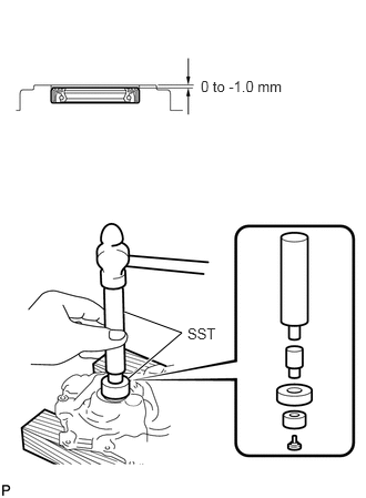
Using SST and a hammer, tap in a new oil pump seal until its surface is flush with the oil pump assembly.
- SST
- 09950-60010 (09951-00250, 09952-06010)
09950-70010 (09951-07100, 09951-00410)
- NOTICE:
- ·
Do not tap the oil seal at an angle.
·Keep the seal lip free of foreign matter.
- Oil seal tap in depth:
0 to -1.0 mm (0 to -0.0393 in.)
Apply MP grease to the oil pump seal lip.
2.INSTALL TAPER SCREW PLUG
Clean and degrease the threads of the taper screw plug and threaded hole of the oil pump assembly.
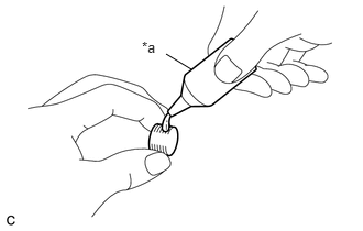
| *a | Adhesive |
Apply adhesive to the 2 or 3 threads of the taper screw plug.
- Adhesive:
Toyota Genuine Adhesive 1324, Three Bond 1324 or equivalent
- NOTICE:
-
To prevent contamination by foreign matter, install immediately after applying adhesive.
Using an 8 mm hexagon wrench, install the taper screw plug to the oil pump assembly.
- Torque:
- 15 N*m (153 kgf*cm, 11 ft.*lbf)
- NOTICE:
-
Do not start the engine for at least 1 hour after installation.
15100
3.INSTALL OIL PUMP ASSEMBLY
Install 2 new O-rings to the cylinder block sub-assembly and oil pan sub-assembly.
Clean the contact surfaces of the oil pump assembly, cylinder head sub-assembly, cylinder block sub-assembly and oil pan sub-assembly.
Apply seal packing to the oil pump assembly, cylinder head sub-assembly and cylinder block sub-assembly as shown in the illustration.
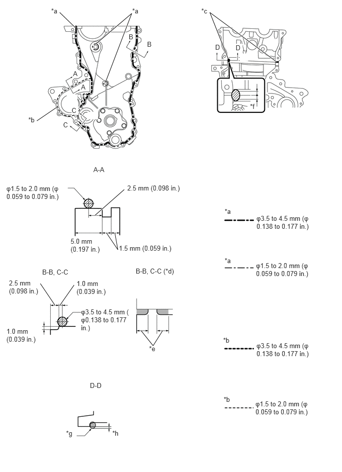
| *a | Seal Packing (Other part) | *b | Seal Packing (Water Pump part) |
| *c | Apply enough seal packing so that it will spread to the inner side | *d | After assembly |
| *e | 2.5 mm (0.098 in.) or more | *f | Seal Packing application width 10 mm or more |
| *g | φ10.0 mm (φ0.394 in.) or more | *h | Apply enough seal packing so that it will protrude beyond the Oil Pump Assembly installation surface |
- Seal packing:
Water pump part: Toyota Genuine Seal Packing 1282B: Three Bond 1282B or equivalent
Other part: Toyota Genuine Seal Packing Black: Three Bond 1207B or equivalent
- NOTICE:
- ·
Install the oil pump assembly within 3 minutes and tighten the bolts and nut within 15 minutes of applying seal packing.
·Do not expose the seal to engine oil for at least 2 hours after the installation.
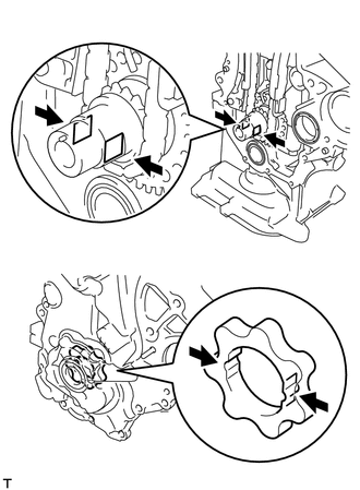
Align the keyway of the oil pump rotor with the rectangular portion of the crankshaft, and slide the oil pump into place.
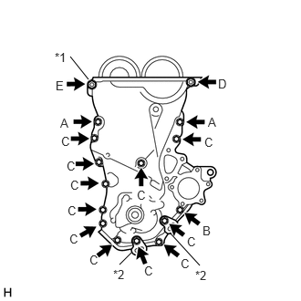
| *1 | Nut |
| *2 | Wire Harness Clamp Bracket |
Install the oil pump assembly and 2 wire harness clamps with the 15 bolts and nut. Tighten the bolts and nut uniformly in several steps.
- Torque:
- Bolt A : 32 N*m (326 kgf*cm, 24 ft.*lbf)
- Bolt B, C : 12 N*m (122 kgf*cm, 9 ft.*lbf)
- Bolt D : 24 N*m (245 kgf*cm, 18 ft.*lbf)
- Nut E : 24 N*m (245 kgf*cm, 18 ft.*lbf)
- NOTICE:
- ·
Be careful not to disturb the seal packing.
·After installing the oil pump assembly, install the engine mounting bracket RH and engine water pump assembly within 15 minutes.
- Bolt Length:
Item Length Bolt A 30 mm (1.181 in.) Bolt B 35 mm (1.378 in.) Bolt C 20 mm (0.787 in.) Bolt D (Double ended bolt) 20 mm (0.787 in.)
12315A
4.INSTALL ENGINE MOUNTING BRACKET RH
Install the engine mounting bracket RH to the oil pump assembly with the 4 bolts.
- Torque:
- 55 N*m (561 kgf*cm, 41 ft.*lbf)
16100
5.INSTALL ENGINE WATER PUMP ASSEMBLY
16173
6.INSTALL WATER PUMP PULLEY
11101J
7.INSTALL CAMSHAFT TIMING OIL CONTROL VALVE ASSEMBLY
15100Q
8.INSTALL CRANKSHAFT POSITION SENSOR
13407
9.INSTALL CRANKSHAFT DAMPER SUB-ASSEMBLY
Align the pin hole of the crankshaft damper sub-assembly with the pin of the crankshaft and install the crankshaft damper sub-assembly.
Temporarily tighten the bolt to the crankshaft damper sub-assembly.
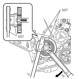
| *a | Hold |
| *b | Turn |
Using SST, tighten the bolt of the crankshaft damper sub-assembly.
- SST
- 09213-14010 (91651-60865)
09330-00021 (09330-00030)
- Torque:
- 128 N*m (1305 kgf*cm, 94 ft.*lbf)
- NOTICE:
-
Check the SST installation positions when installing them, to avoid the SST fixing bolts from coming into contact with the oil pump assembly.
12305
10.INSTALL ENGINE MOUNTING INSULATOR SUB-ASSEMBLY RH
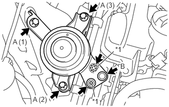
| *1 | Nut |
Temporarily install the engine mounting insulator sub-assembly RH to the engine mounting bracket RH and vehicle with the 4 bolts and 2 nuts.
Tighten the 3 bolts A in the order shown in the illustration.
- Torque:
- Bolt A : 52 N*m (530 kgf*cm, 38 ft.*lbf)
Tighten the bolt B and 2 nuts.
- Torque:
- Bolt B, Nut : 52 N*m (530 kgf*cm, 38 ft.*lbf)
11201
11.INSTALL CYLINDER HEAD COVER SUB-ASSEMBLY
23820
12.CONNECT FUEL VAPOR FEED HOSE ASSEMBLY
12261
13.CONNECT VENTILATION HOSE
19500D
14.INSTALL NO. 1 IGNITION COIL
27060
15.INSTALL GENERATOR WITH REGULATOR ASSEMBLY
17410
16.INSTALL FRONT EXHAUST PIPE ASSEMBLY
57533B
17.INSTALL FRONT FLOOR CENTER BRACE
58910C
18.INSTALL REAR CONSOLE BOX ASSEMBLY (w/ Console Box Lid)
58910C
19.INSTALL REAR CONSOLE BOX ASSEMBLY (w/o Console Box Lid)
20.CONNECT CABLE TO NEGATIVE BATTERY TERMINAL
- Torque:
- 5.4 N*m (55 kgf*cm, 48 in.*lbf)
21.ADD ENGINE OIL
22.ADD ENGINE COOLANT
23.INSPECT ENGINE OIL LEVEL
24.INSPECT FOR ENGINE OIL LEAK
25.INSPECT FOR COOLANT LEAK
26.INSPECT FOR EXHAUST GAS LEAK
51441C
27.INSTALL ENGINE UNDER COVER RH (w/o Metal Type Under Cover)
51405A
28.INSTALL NO. 1 ENGINE UNDER COVER SUB-ASSEMBLY (w/ Metal Type Under Cover)
51451A
29.INSTALL CENTER ENGINE UNDER COVER (w/ Metal Type Under Cover)
30.INSTALL FRONT WHEEL RH
- Torque:
- 103 N*m (1050 kgf*cm, 76 ft.*lbf)