BRAKE SYSTEM (OTHER) BRAKE BOOSTER(for LHD) INSTALLATION
PROCEDURE

 44610
1.INSTALL BRAKE BOOSTER ASSEMBLY
Install a new brake booster gasket to the brake booster assembly.
Temporarily install the brake booster assembly to the body with the 4 nuts.
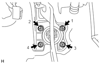
Tighten the 4 nuts in the order shown in the illustration.
- Torque:
- 9.0 N*m (92 kgf*cm, 80 in.*lbf)
for 1NR-FE, 2NR-FE:
Connect the vacuum sensor assembly connector.
47264D
2.INSTALL BRAKE MASTER CYLINDER PUSH ROD CLEVIS
Install the clevis lock nut and brake master cylinder push rod clevis to the brake booster assembly.
- HINT:
-
Tighten the clevis lock nut after adjusting the brake pedal height.

|
Lithium Soap Base Glycol Grease |
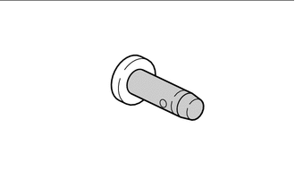
Apply lithium soap base glycol grease to the push rod pin.
Install the brake master cylinder push rod clevis to the brake pedal sub-assembly with the push rod pin and a new clip.
- NOTICE:
-
Install the push rod pin from the right side of the vehicle.
47101A
3.INSTALL BRAKE PEDAL RETURN SPRING
4.INSTALL WIRE HARNESS
84340
5.INSTALL STOP LIGHT SWITCH ASSEMBLY
44772
6.CONNECT CHECK VALVE TO CONNECTOR TUBE HOSE (for Automatic Transaxle and CVT)
Connect the 2 check valve to connector tube hoses to the 2 brake vacuum check valve assemblies with the 2 hose clips.
44772
7.CONNECT CHECK VALVE TO CONNECTOR TUBE HOSE (for Manual Transaxle)
Connect the check valve to connector tube hose to the brake vacuum check valve assembly with the hose clip.
47315
8.INSTALL FRONT NO. 5 BRAKE TUBE (w/ ABS,VSC)
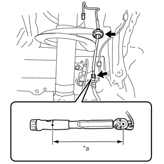
| *a | Torque Wrench Fulcrum Length |
Install the front No. 5 brake tube and grommet to the body.
Using a 10 mm union nut wrench, connect the front No. 5 brake tube to the front flexible hose while holding the front flexible hose with the wrench.
- Torque:
- Specified tightening torque : 15.2 N*m (155 kgf*cm, 11 ft.*lbf)
- HINT:
- ·
Calculate the torque wrench reading when changing the fulcrum length of the torque wrench.
Click hereGeneral>INTRODUCTION>REPAIR INSTRUCTION>PRECAUTION
·When using a union nut wrench (fulcrum length of 22 mm (0.866 in.)) + torque wrench (fulcrum length of 162 mm (6.38 in.)) (A): 13.4 N*m (137 kgf*cm, 10 ft.*lbf)
44510
9.INSTALL BRAKE ACTUATOR ASSEMBLY (w/ ABS,VSC)
except CVT:
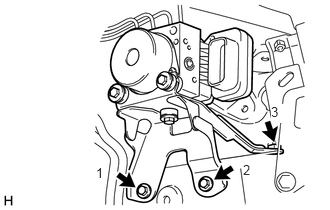
Install the brake actuator assembly with the brake actuator bracket assembly with the 3 bolts in the sequence shown in the illustration.
- Torque:
- 19 N*m (194 kgf*cm, 14 ft.*lbf)
- NOTICE:
- ·
Do not damage the brake tubes or wire harness.
·Do not carry the brake actuator assembly with the brake actuator bracket assembly by the connector.
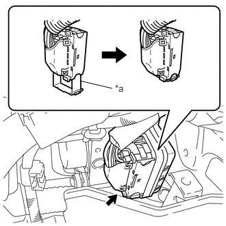
| *a | Lock Lever |
Connect the brake actuator connector.
- NOTICE:
- ·
Make sure that the connector is locked securely.
·Make sure that the brake actuator connector can be connected smoothly. Do not allow entry of water, oil or dirt.
for CVT:
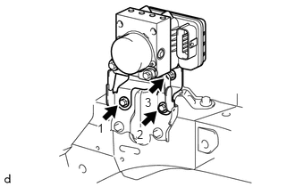
Install the brake actuator assembly with the brake actuator bracket assembly with the 3 bolts in the sequence shown in the illustration.
- Torque:
- 19 N*m (194 kgf*cm, 14 ft.*lbf)
- NOTICE:
- ·
Do not damage the brake tubes or wire harness.
·Do not carry the brake actuator assembly with the brake actuator bracket assembly by the connector.
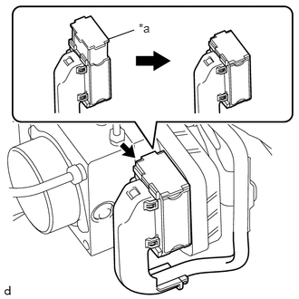
| *a | Lock Lever |
Connect the brake actuator connector.
- NOTICE:
- ·
Make sure that the connector is locked securely.
·Make sure that the brake actuator connector can be connected smoothly. Do not allow entry of water, oil or dirt.
47150
10.INSTALL PROPORTIONING VALVE ASSEMBLY (w/o ABS,VSC)
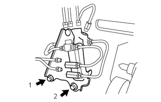
Install the proportioning valve bracket with the proportioning valve assembly with the 2 bolts in the order shown in the illustration.
- Torque:
- 19 N*m (194 kgf*cm, 14 ft.*lbf)
45209
11.INSTALL STEERING SLIDING YOKE SUB-ASSEMBLY
45259A
12.INSTALL COLUMN HOLE COVER SILENCER SHEET
55432B
13.INSTALL LOWER INSTRUMENT PANEL FINISH PANEL
55606
14.INSTALL NO. 1 INSTRUMENT PANEL UNDER COVER SUB-ASSEMBLY
47201
15.INSTALL BRAKE MASTER CYLINDER SUB-ASSEMBLY
16.INSPECT AND ADJUST BRAKE PEDAL