DRIVE SHAFT / PROPELLER SHAFT FRONT DRIVE SHAFT ASSEMBLY REMOVAL
CAUTION / NOTICE / HINT
- HINT:
- ·
Use the same procedure for the RH side and LH side.
·The procedure listed below is for the LH side.
PROCEDURE

 1.REMOVE FRONT WHEELS
51442C
2.REMOVE ENGINE UNDER COVER LH (w/o Metal Type Under Cover)
for 2NR-FE:
Click hereEngine / Hybrid System>2NR-FE ENGINE MECHANICAL>ENGINE ASSEMBLY(for CVT)>REMOVAL
51441C
3.REMOVE ENGINE UNDER COVER RH (w/o Metal Type Under Cover)
for 2NR-FE:
Click hereEngine / Hybrid System>2NR-FE ENGINE MECHANICAL>ENGINE ASSEMBLY(for CVT)>REMOVAL
51451A
4.REMOVE CENTER ENGINE UNDER COVER (w/ Metal Type Under Cover)
for 2NR-FE:
Click hereEngine / Hybrid System>2NR-FE ENGINE MECHANICAL>ENGINE ASSEMBLY(for CVT)>REMOVAL
51405A
5.REMOVE NO. 1 ENGINE UNDER COVER SUB-ASSEMBLY (w/ Metal Type Under Cover)
for 2NR-FE:
Click hereEngine / Hybrid System>2NR-FE ENGINE MECHANICAL>ENGINE ASSEMBLY(for CVT)>REMOVAL
6.DRAIN CONTINUOUSLY VARIABLE TRANSAXLE FLUID (for CVT)
for K312:
Click hereDrivetrain>K312 CVT>OIL PAN>REMOVAL
for K411:
Click hereDrivetrain>K411 CVT>OIL PAN>REMOVAL
7.DRAIN AUTOMATIC TRANSAXLE FLUID (for Automatic Transaxle)
for U340E:
Click hereDrivetrain>U340E AUTOMATIC TRANSMISSION / TRANSAXLE>VALVE BODY ASSEMBLY>REMOVAL
for U441E:
Click hereDrivetrain>U441E AUTOMATIC TRANSMISSION / TRANSAXLE>VALVE BODY ASSEMBLY>REMOVAL
8.DRAIN MANUAL TRANSAXLE OIL (for Manual Transaxle)
43502H
9.REMOVE FRONT AXLE SHAFT NUT
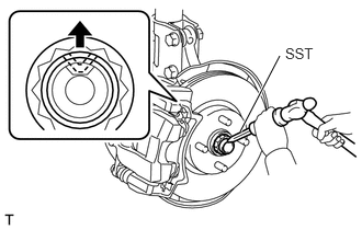
Using SST and a hammer, release the staked part of the front axle shaft nut.
- SST
- 09930-00010
- NOTICE:
-
Loosen the staked part of the nut completely, otherwise the threads of the front drive shaft assembly may be damaged.
Using a 30 mm deep socket wrench, remove the front axle shaft nut.
- HINT:
-
Keep depressing the brake pedal to prevent the front drive shaft assembly from rotating.
47313A
10.SEPARATE FRONT FLEXIBLE HOSE (w/ ABS)
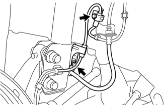
Remove the 2 bolts to separate the front flexible hose and front speed sensor wire from the front shock absorber assembly and body.
47313A
11.SEPARATE FRONT FLEXIBLE HOSE (w/o ABS)
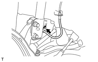
Remove the bolt to separate the front flexible hose from the front shock absorber assembly.
45047
12.SEPARATE TIE ROD END SUB-ASSEMBLY
48819A
13.REMOVE FRONT STABILIZER BOLT
48069
14.SEPARATE FRONT LOWER NO. 1 SUSPENSION ARM SUB-ASSEMBLY
15.SEPARATE FRONT AXLE ASSEMBLY
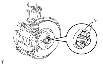
| *a | Matchmark |
Put matchmarks on the front drive shaft assembly and front axle hub sub-assembly.
Using a plastic hammer, tap the end of the front drive shaft assembly and separate the fitting between the front drive shaft assembly and front axle assembly.
- NOTICE:
-
Be careful not to damage the front drive shaft assembly.
- HINT:
-
If it is difficult to separate the front drive shaft assembly from the front axle assembly, tap the end of the front drive shaft assembly using a brass bar and a hammer.
43498A
16.REMOVE DRIVE SHAFT HEAT INSULATOR SUB-ASSEMBLY
for CVT with 1NR-FE:
Click hereEngine / Hybrid System>1NR-FE ENGINE MECHANICAL>ENGINE ASSEMBLY(for CVT)>REMOVAL
for Manual Transaxle with 1NR-FE and 2NR-FE:
Click hereEngine / Hybrid System>2NR-FE ENGINE MECHANICAL>ENGINE ASSEMBLY(for Manual Transaxle)>REMOVAL
43420
17.REMOVE FRONT DRIVE SHAFT ASSEMBLY LH
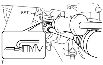
Using SST, remove the front drive shaft assembly LH from the transaxle.
- SST
- 09520-01010
09520-24010 (09520-32040)
- NOTICE:
- ·
Do not damage the front drive shaft oil seal LH.
·Do not damage the front axle inboard joint boot.
·Do not drop the front drive shaft assembly LH.
43410
18.REMOVE FRONT DRIVE SHAFT ASSEMBLY RH
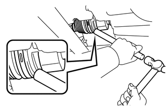
Using a brass bar and a hammer, remove the front drive shaft assembly RH from the transaxle.
- NOTICE:
- ·
Do not damage the front drive shaft oil seal RH.
·Do not damage the front axle inboard joint boot.
·Do not drop the front drive shaft assembly RH.
43420G
19.REMOVE FRONT DRIVE SHAFT HOLE SNAP RING
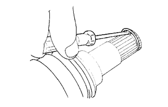
Using a screwdriver, remove the front drive shaft hole snap ring from the front drive shaft assembly.
20.FIX FRONT AXLE ASSEMBLY
- HINT:
-
The hub bearing could be damaged if it is subjected to the vehicle's full weight, such as when moving the vehicle with the front drive shaft assembly removed. If it is absolutely necessary to place the vehicle's full weight on the hub bearing, first support it with SST.
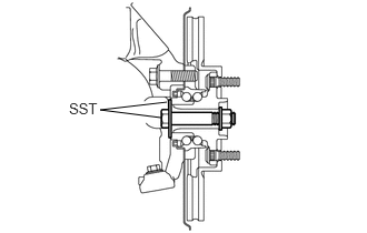
- SST
- 09608-16042 (09608-02021, 09608-02041)