WINDOW / GLASS POWER WINDOW CONTROL SYSTEM Driver Side Power Window Auto Up / Down Function does not Operate with Power Window Master Switch
DESCRIPTION
If the manual up and down function can be performed but the auto up and down function cannot, then the fail-safe mode may be functioning.
If the power window initialization has not been performed, the auto up and down function will not operate.
Click hereVehicle Exterior>WINDOW / GLASS>POWER WINDOW CONTROL SYSTEM>INITIALIZATION
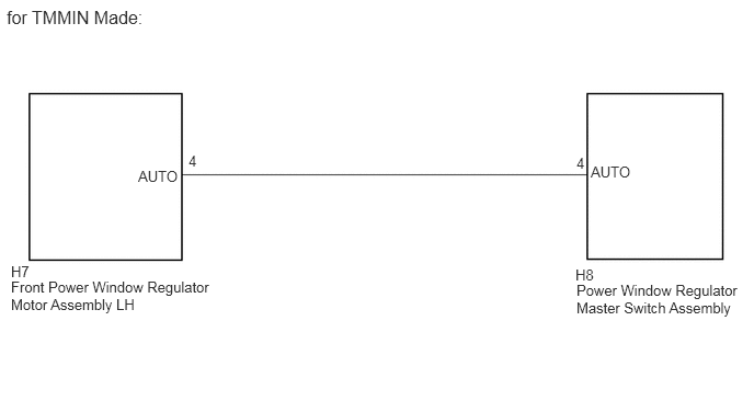
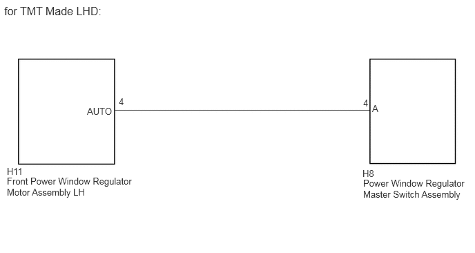
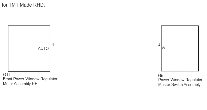
WIRING DIAGRAM
CAUTION / NOTICE / HINT
- NOTICE:
- ·
When the front power window regulator motor assembly (driver side) is reinstalled or replaced, the power window control system must be initialized.
·Replacing the door glass or door glass run may cause a difference to exist between the current door glass position and the position memorized in the ECU. In this case, the jam protection function may work improperly. Return the system to the pre-initialized condition and reinitialize the system.
1.Disconnect the power window regulator motor connector during power window operation. This will return the motor to the pre-initialized condition.
- HINT:
-
The auto up function will not work unless initialization is completed.
PROCEDURE
Check vehicle type.
- Result:
Result Proceed to for TMMIN Made A for TMT Made B
A
B
Remove the power window regulator master switch assembly.
Click hereVehicle Exterior>WINDOW / GLASS>POWER WINDOW MASTER SWITCH(for TMMIN Made)>REMOVAL
Inspect the power window regulator master switch assembly.
Click hereVehicle Exterior>WINDOW / GLASS>POWER WINDOW MASTER SWITCH(for TMMIN Made)>INSPECTION
- Result:
Proceed to OK NG
OK
NG
Disconnect the H8 power window regulator master switch assembly connector.
Disconnect the H7 front power window regulator motor assembly LH connector.
Measure the resistance according to the value(s) in the table below.
- Standard Resistance:
Tester Connection Condition Specified Condition H8-4 (AUTO) - H7-4
(AUTO)Always Below 1 Ω H7-4 (AUTO) or H8-4 (AUTO) - Body
groundAlways 10 kΩ or higher
- Result:
Proceed to OK NG
OK
NG
Initialize the front power window regulator motor assembly LH.
Click hereVehicle Exterior>WINDOW / GLASS>POWER WINDOW CONTROL SYSTEM>INITIALIZATION
- Result:
Proceed to NEXT
NEXT
Check that the driver side door power window moves when the auto up and down function of the power window regulator master switch assembly and are operated.
Click hereVehicle Exterior>WINDOW / GLASS>POWER WINDOW CONTROL SYSTEM>OPERATION CHECK
- OK:
Driver side auto up and down function is normal.
- Result:
Proceed to OK NG
OK
NG
Remove the power window regulator master switch assembly.
Click hereVehicle Exterior>WINDOW / GLASS>POWER WINDOW MASTER SWITCH(for TMT Made)>REMOVAL
Inspect the power window regulator master switch assembly.
Click hereVehicle Exterior>WINDOW / GLASS>POWER WINDOW MASTER SWITCH(for TMT Made)>INSPECTION
- Result:
Proceed to OK NG
OK
NG
for LHD
Disconnect the H8 power window regulator master switch assembly connector.
Disconnect the H11 front power window regulator motor assembly LH connector.
Measure the resistance according to the value(s) in the table below.
- Standard Resistance:
Tester Connection Condition Specified Condition H8-4 (A) - H11-4 (AUTO) Always Below 1 Ω H8-4 (A) or H11-4 (AUTO) - Body ground Always 10 kΩ or higher
for RHD
Disconnect the G5 power window regulator master switch assembly connector.
Disconnect the G11 front power window regulator motor assembly RH connector.
Measure the resistance according to the value(s) in the table below.
- Standard Resistance:
Tester Connection Condition Specified Condition G5-4 (A) - G11-4 (AUTO) Always Below 1 Ω G11-4 (AUTO) or G5-4 (A) - Body ground Always 10 kΩ or higher
- Result:
Proceed to OK NG
OK
NG
Initialize the front power window regulator motor assembly (driver side).
Click hereVehicle Exterior>WINDOW / GLASS>POWER WINDOW CONTROL SYSTEM>INITIALIZATION
- Result:
Proceed to NEXT
NEXT
Check that the driver side door power window moves when the auto up and down function of the power window regulator master switch assembly and are operated.
Click hereVehicle Exterior>WINDOW / GLASS>POWER WINDOW CONTROL SYSTEM>OPERATION CHECK
- OK:
Driver side auto up and down function is normal.
- Result:
Proceed to OK NG
OK
NG