HEATING / AIR CONDITIONING COMPRESSOR(for M15A-FXE) REMOVAL
CAUTION / NOTICE / HINT
- CAUTION:
- ·
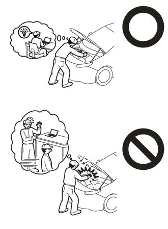
This vehicle has contains high voltage circuits standardized with orange colored wiring and connectors, so follow the instructions in this manual to perform the procedures correctly.
Click hereEngine / Hybrid System>HYBRID / BATTERY CONTROL>HYBRID CONTROL SYSTEM>PRECAUTION
·If the correct procedures are not followed according to the instructions in this manual, there is a danger of electric shock from the high voltage circuits.
·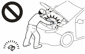
Be sure to wear insulating gloves when working on high voltage wiring or components.
·If work is performed without wearing insulating gloves, there is a danger of electric shock.
PROCEDURE

 1.RECOVER REFRIGERANT FROM REFRIGERATION SYSTEM
G3834
2.REMOVE SERVICE PLUG GRIP
82121
3.DISCONNECT ENGINE WIRE
4.REMOVE CONNECTOR COVER ASSEMBLY
5.CHECK TERMINAL VOLTAGE
6.INSTALL CONNECTOR COVER ASSEMBLY
82121
7.CONNECT ENGINE WIRE
51451A
8.REMOVE CENTER ENGINE UNDER COVER
88704
9.DISCONNECT SUCTION HOSE SUB-ASSEMBLY
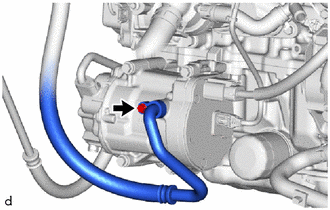
Remove the bolt to disconnect the suction hose sub-assembly from the compressor with motor assembly.
Remove the O-ring from the suction hose sub-assembly.
- NOTICE:
-
Seal the openings of the disconnected parts using vinyl tape to prevent moisture and foreign matter from entering them.
88703
10.DISCONNECT DISCHARGE HOSE SUB-ASSEMBLY
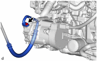
Remove the bolt and disconnect the discharge hose sub-assembly from the compressor with motor assembly.
Remove the O-ring from the discharge hose sub-assembly.
- NOTICE:
-
Seal the openings of the disconnected parts using vinyl tape to prevent moisture and foreign matter from entering them.
88370
11.REMOVE COMPRESSOR WITH MOTOR ASSEMBLY
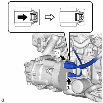
| *a | Connector A |
| *b | Connector B |
Slide the green-colored lock of the connector A as shown in the illustration to release it and disconnect the connector.
- CAUTION:
-
Make sure to wear insulating gloves.
- NOTICE:
-
Insulate the disconnected terminals and connector with insulating tape.
Disconnect the connector B.
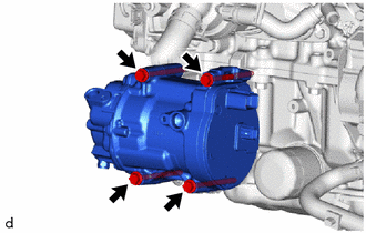
Remove the 4 bolts and compressor with motor assembly.