1KR-FE EMISSION CONTROL EGR VALVE INSTALLATION
PROCEDURE

 25620
1.INSTALL EGR VALVE ASSEMBLY
- HINT:
-
Perform "Inspection After Repair" after replacing the EGR valve assembly.
-
Click hereEngine / Hybrid System>1KR-FE (ENGINE CONTROL)>SFI SYSTEM>INITIALIZATION
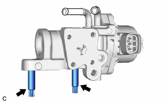
Using an E8 "TORX" socket wrench, install the 2 stud bolts to the EGR valve assembly.
- HINT:
-
If a stud bolt is deformed or the threads are damaged, replace it.
- Torque:
- 7.5 N*m (76 kgf*cm, 66 in.*lbf)
Install a new No. 1 EGR cooler gasket to the EGR valve assembly.
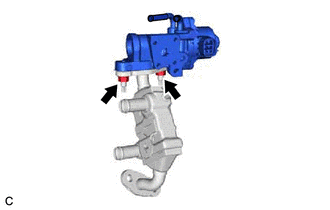
Install the EGR valve assembly to the EGR cooler assembly with the 2 nuts.
- Torque:
- 32 N*m (326 kgf*cm, 24 ft.*lbf)
Connect the No. 3 water by-pass hose to the EGR valve assembly and slide the clip to secure it.
2.INSTALL EGR VALVE WITH COOLER ASSEMBLY
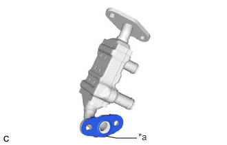
| *a | Convex Portion |
Install a new EGR valve gasket to the EGR cooler assembly as shown in the illustration.
Temporarily install the EGR valve assembly with the EGR cooler assembly with the 2 bolts and 2 nuts.
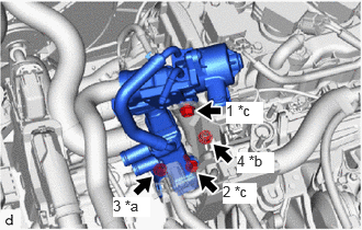
| *a | Nut (A) |
| *b | Nut (B) |
| *c | Bolt |
Tighten the 2 bolts and 2 nuts in the order shown in the illustration.
- Torque:
- Bolt and Nut (A) : 28 N*m (286 kgf*cm, 21 ft.*lbf)
- Nut (B) : 22.4 N*m (228 kgf*cm, 17 ft.*lbf)
Engage the wire harness clamp and connect the engine wire.
Connect the No. 4 water by-pass hose assembly to the EGR cooler assembly and slide the clip to secure it.
Connect the water hose sub-assembly to the EGR cooler assembly and slide the clip to secure it.
Connect the No. 2 water by-pass hose assembly to the EGR valve assembly and slide the clip to secure it.
Connect the EGR valve assembly connector.
25601
3.INSTALL NO. 1 EGR PIPE SUB-ASSEMBLY
Install the EGR pipe gasket to the intake manifold.
Install the EGR pipe gasket to the NO.1 EGR pipe sub-assembly.
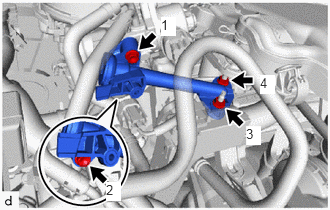
Tighten the 2 nuts and 2 bolts in the order shown in the illustration.
- Torque:
- 10 N*m (102 kgf*cm, 7 ft.*lbf)
17650G
4.INSTALL DUTY VACUUM SWITCHING VALVE
5.INSTALL AIR CLEANER CAP WITH AIR CLEANER HOSE
6.ADD ENGINE COOLANT
7.INSPECT FOR COOLANT LEAK