M15A-FXE ENGINE MECHANICAL ENGINE UNIT REMOVAL
CAUTION / NOTICE / HINT
The necessary procedures (adjustment, calibration, initialization, or registration) that must be performed after parts are removed and installed, or replaced during engine unit removal/installation are shown below.
| Replaced Part or Performed Procedure | Necessary Procedure | Effect/Inoperative Function when Necessary Procedure not Performed | Link |
|---|---|---|---|
·
Throttle body with motor assembly ·
Cleaning the deposits from the throttle body with motor assembly ·
Cam timing control motor with EDU assembly ·
Removal and installation of a cam timing control motor with EDU assembly ·
Camshaft timing gear assembly ·
Removal and installation of a camshaft timing gear assembly ·
Engine assembly ·
Cylinder head sub-assembly ·
Camshaft (for intake or exhaust camshaft) ·
Camshaft timing exhaust gear assembly ·
Mass air flow meter sub-assembly ·
Port fuel injector assembly ·
Direct fuel injector assembly ·
Fuel pump (for low pressure side) ·
Fuel pump assembly (for high pressure side) ·
Fuel pressure sensor (fuel delivery pipe with sensor sub-assembly) (for low pressure side) ·
Fuel pressure sensor (for high pressure side) ·
Air fuel ratio sensor (sensor 1) ·
Air fuel ratio sensor (sensor 2) ·
Engine coolant temperature sensor ·
Spark plug ·
Ignition coil assembly ·
EGR valve assembly ·
Air leaks from intake system ·
Gas leaks from exhaust system ·
Knock control sensor |
Inspection after repair | ·
Poor idle, etc. ·
Engine start function, etc. |
( ) |
PROCEDURE

 89467B
1.REMOVE AIR FUEL RATIO SENSOR
89481B
2.REMOVE DIFFERENTIAL PRESSURE SENSOR (w/ Differential Pressure Sensor)
25733A
3.REMOVE NO. 1 VACUUM PIPE (w/ Differential Pressure Sensor)
17167
4.REMOVE NO. 1 EXHAUST MANIFOLD HEAT INSULATOR
17118
5.REMOVE MANIFOLD STAY
17141
6.REMOVE EXHAUST MANIFOLD
22030
7.REMOVE THROTTLE BODY WITH MOTOR ASSEMBLY
22271
8.REMOVE THROTTLE BODY GASKET
23250
9.REMOVE FUEL INJECTOR ASSEMBLY
82219C
10.REMOVE SENSOR WIRE
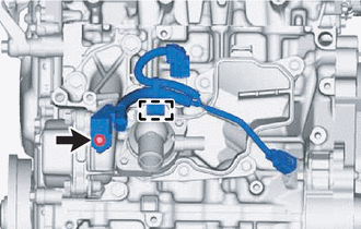
Disengage the clamp.
Remove the bolt and sensor wire from the water inlet with thermostat sub-assembly.
19500
11.REMOVE IGNITION COIL ASSEMBLY
11452D
12.REMOVE OIL LEVEL GAGE GUIDE
Remove the engine oil level dipstick.
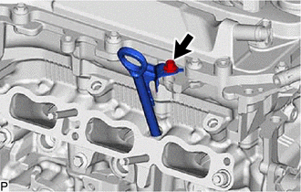
Using an 8 mm socket wrench, remove the bolt and engine oil level dipstick guide from the cylinder head sub-assembly.
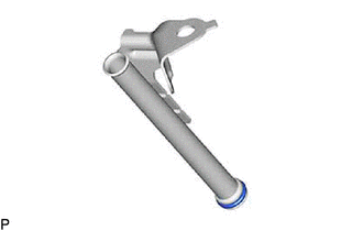
Remove the O-ring from the engine oil level dipstick guide.
13.REMOVE NO. 1 WATER BY-PASS PIPE ASSEMBLY
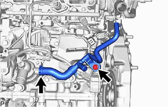
Remove the bolt.
Slide the clip and remove the water by-pass hose assembly from the water inlet with thermostat sub-assembly.
16281
14.REMOVE NO. 4 WATER BY-PASS HOSE
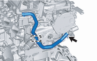
Disengage the clamp to separate the No. 4 water by-pass hose.
Slide the clip and remove the No. 4 water by-pass hose from the water outlet.
12262
15.REMOVE NO. 2 VENTILATION HOSE
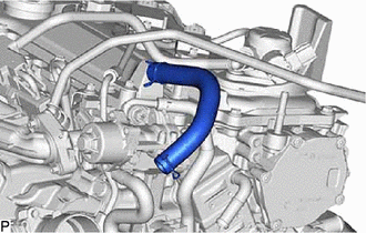
Slide the hose clip and remove the No. 2 ventilation hose from the cylinder head cover sub-assembly.
16.REMOVE WIRE HARNESS CLAMP BRACKET
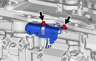
Using an 8 mm socket wrench, remove the 2 bolts and wire harness clamp bracket from the camshaft housing sub-assembly.
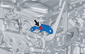
Remove the bolt and wire harness clamp bracket from the camshaft housing sub-assembly.