1KR-FE COOLING RADIATOR INSTALLATION
PROCEDURE

 1.INSTALL RADIATOR DRAIN COCK PLUG
Install the O-ring to the radiator drain cock plug.
- NOTICE:
-
Replace the O-ring if it is damaged.
Install the radiator drain cock plug.
16535
2.INSTALL LOWER RADIATOR SUPPORT
Install the 2 lower radiator supports to the radiator assembly.
16523A
3.INSTALL RADIATOR SUPPORT CUSHION
Install the 2 radiator support cushions to the radiator assembly.
16400
4.INSTALL RADIATOR ASSEMBLY
Engage the 2 claws and 2 guides to install the fan shroud to the radiator assembly.
- NOTICE:
-
Do not damage the radiator assembly when installing the fan shroud.
Install the radiator assembly together with the fan shroud to the vehicle body.
- NOTICE:
-
Do not apply excessive force to the cooler condenser assembly or pipe when installing the radiator assembly with the fan with motor assembly.
88460
5.INSTALL COOLER CONDENSER ASSEMBLY
Engage the 2 claws and 2 guides to install the cooler condenser assembly to the radiator assembly.
- NOTICE:
-
Do not damage the cooler condenser assembly or radiator assembly when installing the cooler condenser assembly.
16572D
6.CONNECT NO. 2 RADIATOR HOSE
Connect the No. 2 radiator hose to the radiator assembly and slide the clip to secure it.
16573B
7.CONNECT NO. 3 RADIATOR HOSE
Connect the No. 3 radiator hose to the radiator assembly and slide the clip to secure it.
16502
8.INSTALL WATER FILLER SUB-ASSEMBLY
Install the water filler sub-assembly to the fan shroud with the 2 bolts.
- Torque:
- 5 N*m (51 kgf*cm, 44 in.*lbf)
Engage the 2 clamps and connect the wire harness.
Connect the connector.
9.CONNECT RADIATOR RESERVOIR TANK HOSE
Connect the radiator reservoir tank hose to the water filler sub-assembly.
16261G
10.CONNECT NO. 1 WATER BY-PASS HOSE
Connect the No. 1 water by-pass hose to the radiator assembly and slide the clip to secure it.
Engage the clamp.
16595D
11.INSTALL NO. 1 RADIATOR AIR GUIDE LH
Engage the claw and guide to install the No. 1 radiator air guide LH.
Engage the 2 clamps and connect the wire harness.
16561D
12.INSTALL NO. 1 RADIATOR TO SUPPORT SEAL
Engage the claw and guide to install the No. 1 radiator to support seal.
16562L
13.INSTALL NO. 2 RADIATOR TO SUPPORT SEAL
16695A
14.INSTALL FRONT RADIATOR SIDE AIR GUIDE PLATE LH
16691A
15.INSTALL FRONT RADIATOR SIDE AIR GUIDE PLATE RH
53213C
16.INSTALL UPPER FRONT RADIATOR SUPPORT
When replacing upper front radiator support:
Align the upper front radiator support according to the reference values and point-to-point distances, and temporarily install it with the 4 bolts.
for Reference Values:
Body Repair Manual > Vehicle Exterior > BODY PANEL > RADIATOR SUPPORT> REFERENCE VALUE
for Point-to-point Distances:
Body Repair Manual > Vehicle Exterior > BODY DIMENSIONS > ENGINE COMPARTMENT REFERENCE VALUES > POINT-TO-POINT DISTANCE
When reusing upper front radiator support:
Align the upper front radiator support with the matchmark positions and temporarily install it with the 4 bolts as shown in the illustration.
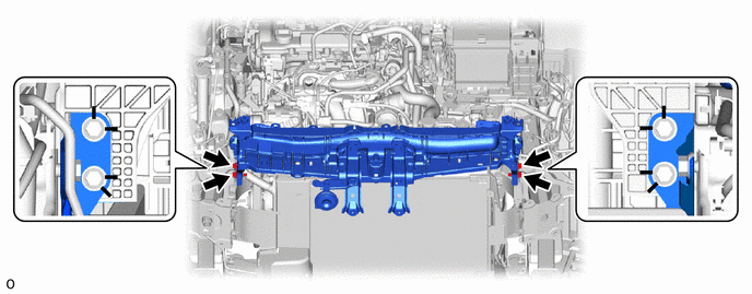
Tighten the 4 bolts.
- Torque:
- 7.1 N*m (72 kgf*cm, 63 in.*lbf)
Connect the connector.
Connect the wire harness with the bolt.
- Torque:
- 10 N*m (102 kgf*cm, 7 ft.*lbf)
Engage the 3 clamps and connect the wire harness.
Connect the 2 airbag connectors.
- NOTICE:
-
When connecting any airbag connector, take care not to damage the airbag wire harness.
- HINT:
-
Refer to How to Connect or Disconnect Airbag Connector:
Connect the hood lock control cable assembly.
17701
17.INSTALL AIR CLEANER CASE SUB-ASSEMBLY
Engage the 3 grommets to install the air cleaner case sub-assembly to the vehicle body.
Connect the air cleaner hose assembly to the throttle body with motor assembly and tighten the hose clamp.
- Torque:
- 3.0 N*m (31 kgf*cm, 27 in.*lbf)
Connect the No. 2 ventilation hose to the air cleaner hose and slide the clip to secure it.
53510
18.INSTALL HOOD LOCK ASSEMBLY
52131A
19.INSTALL FRONT BUMPER REINFORCEMENT
52611
20.INSTALL FRONT BUMPER ENERGY ABSORBER
16681A
21.INSTALL RADIATOR UPPER AIR GUIDE PLATE
22.INSTALL HEADLIGHT ASSEMBLY LH
for Halogen Headlight:
Click hereVehicle Exterior>LIGHTING (EXT)>HEADLIGHT ASSEMBLY (for Halogen Headlight)>INSTALLATION
for LED Headlight:
Click hereVehicle Exterior>LIGHTING (EXT)>HEADLIGHT ASSEMBLY (for LED Headlight)>INSTALLATION
23.INSTALL HEADLIGHT ASSEMBLY RH
- HINT:
-
Use the same procedure as for the LH side.
24.CONNECT CABLE TO NEGATIVE AUXILIARY BATTERY TERMINAL
25.ADD ENGINE COOLANT
26.INSPECT FOR COOLANT LEAK
51451A
27.INSTALL CENTER ENGINE UNDER COVER
28.INSPECT SRS WARNING LIGHT
53301
29.INSPECT HOOD SUB-ASSEMBLY
53510
30.ADJUST HOOD LOCK ASSEMBLY
31. INITIALIZATION AFTER RECONNECTING BATTERY TERMINAL
Click hereGeneral>SETUP>WHEN DISCONNECTING OR RECONNECTING BATTERY TERMINAL>WORK PROCEDURE
- HINT:
-
When disconnecting and reconnecting the auxiliary battery, there is an automatic learning function that completes learning when the respective system is used.
-
Click hereGeneral>SETUP>WHEN DISCONNECTING OR RECONNECTING BATTERY TERMINAL>AUTOMATIC LEARNING CHART