SEAT BELT REAR SEAT OUTER BELT ASSEMBLY INSTALLATION
CAUTION / NOTICE / HINT
- HINT:
- ·
Use the same procedure for the RH side and LH side.
·The procedure listed below is for the LH side.
PROCEDURE

 73360D
1.INSPECT REAR SEAT OUTER BELT ASSEMBLY
73360D
2.INSTALL REAR SEAT OUTER BELT ASSEMBLY
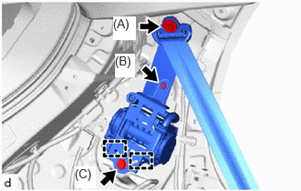
Engage the guides to temporarily install the rear outer belt assembly.
Temporarily install the bolt (B) and bolt (C).
Tighten bolt (B) and then bolt (C).
- Torque:
- Bolt (B) : 12.5 N*m (127 kgf*cm, 9 ft.*lbf)
- Bolt (C) : 42 N*m (428 kgf*cm, 31 ft.*lbf)
Install the shoulder anchor of the rear seat outer belt assembly with the bolt (A).
- Torque:
- Bolt (A) : 42 N*m (428 kgf*cm, 31 ft.*lbf)
Connect the floor anchor of the rear seat outer belt assembly with the bolt.
- Torque:
- 42 N*m (428 kgf*cm, 31 ft.*lbf)
Check that the ELR locks.
- NOTICE:
-
This check should be performed with the rear seat outer belt assembly installed to the vehicle.
With the rear seat outer belt assembly installed to the vehicle, check that the belt locks when it is pulled out quickly.
Connect the pretensioner connector and lock the locking button as shown in the illustration.
- NOTICE:
-
Securely lock the locking button.
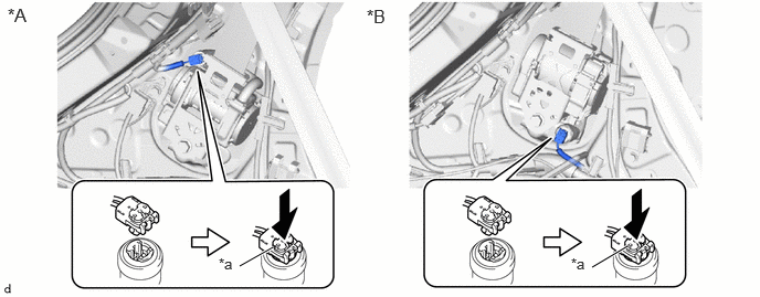
| *A | for TMMF Made | *B | for TMC Made |
| *a | Locking Button | - | - |
Remove the bolt to disconnect the floor anchor of the rear seat outer belt assembly.
62471A
3.INSTALL ROOF SIDE INNER GARNISH
73360D
4.CONNECT REAR SEAT OUTER BELT ASSEMBLY
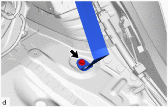
Connect the floor anchor of the rear seat outer belt assembly with the bolt.
- Torque:
- 42 N*m (428 kgf*cm, 31 ft.*lbf)
- NOTICE:
-
Install the floor anchor plate of rear seat outer belt assembly so that a belt consecutive part faces it a vehicle ahead.
64730B
5.INSTALL DECK TRIM SIDE PANEL ASSEMBLY
64714C
6.INSTALL DECK TRIM SIDE COVER
81330
7.INSTALL NO. 1 LUGGAGE COMPARTMENT LIGHT ASSEMBLY (for LH Side)
71303C
8.INSTALL REAR SEATBACK HINGE SUB-ASSEMBLY
62331A
9.CONNECT REAR DOOR OPENING TRIM WEATHERSTRIP
67917F
10.INSTALL REAR DOOR SCUFF PLATE INSIDE
76973F
11.INSTALL REAR UNDER SIDE COVER (for HV Model)
for LH Side:
Click hereVehicle Interior>INTERIOR PANELS / TRIM>ROOF HEADLINING>INSTALLATION
for RH Side:
Click hereVehicle Interior>INTERIOR PANELS / TRIM>ROOF HEADLINING>INSTALLATION
12.INSTALL REAR SEAT ASSEMBLY
64716D
13.INSTALL DECK TRIM REAR COVER
64771G
14.INSTALL SPARE WHEEL COVER
58410B
15.INSTALL DECK BOARD ASSEMBLY (w/ Deck Board)
64330D
16.INSTALL PACKAGE TRAY TRIM PANEL ASSEMBLY (w/ Package Tray Trim)
17.CONNECT CABLE TO NEGATIVE AUXILIARY BATTERY TERMINAL
for M15A-FKS:
Click hereGeneral>MAINTENANCE>M15A-FKS AUXILIARY BATTERY>INSTALLATION
for M15A-FXE:
Click hereGeneral>MAINTENANCE>M15A-FXE AUXILIARY BATTERY>INSTALLATION
for 1KR-FE:
Click hereGeneral>MAINTENANCE>1KR-FE AUXILIARY BATTERY>INSTALLATION
18. INITIALIZATION AFTER RECONNECTING AUXILIARY BATTERY TERMINAL
Click hereGeneral>SETUP>WHEN DISCONNECTING OR RECONNECTING BATTERY TERMINAL>WORK PROCEDURE
- HINT:
-
When disconnecting and reconnecting the auxiliary battery, there is an automatic learning function that completes learning when the respective system is used.
-
Click hereGeneral>SETUP>WHEN DISCONNECTING OR RECONNECTING BATTERY TERMINAL>AUTOMATIC LEARNING CHART
19.PERFORM DIAGNOSTIC SYSTEM CHECK
20.INSPECT SRS WARNING LIGHT