G16E-GTS ENGINE CONTROL KNOCK SENSOR INSTALLATION
CAUTION / NOTICE / HINT
- NOTICE:
-
This procedure includes the installation of small-head bolts. Refer to Small-Head Bolts of Basic Repair Hint to identify the small-head bolts.
-
Click hereGeneral>INTRODUCTION>REPAIR INSTRUCTION>PRECAUTION
PROCEDURE

 89615
1.INSTALL KNOCK SENSOR
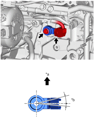
| *a | Top of Vehicle |
| *b | 30° |
Install the knock sensor to the cylinder block sub-assembly with the bolt so that the knock sensor installation position is as shown in the illustration.
- Torque:
- 21 N*m (214 kgf*cm, 15 ft.*lbf)
- NOTICE:
- ·
If the knock sensor has been struck or dropped, replace it.
·Make sure that the knock sensor is in the correct position.
Connect the knock sensor connector.
12211
2.INSTALL NO. 1 VENTILATION CASE
12582D
3.INSTALL NO. 2 CYLINDER BLOCK INSULATOR
16278
4.INSTALL NO. 2 WATER BY-PASS PIPE
16283
5.CONNECT NO. 6 WATER BY-PASS HOSE
Connect the No. 6 water by-pass hose and slide the clip to secure it.
16281
6.INSTALL NO. 4 WATER BY-PASS HOSE
Connect the No. 4 water by-pass hose and slide the clip to secure it.
17111
7.INSTALL INTAKE MANIFOLD
8.PERFORM INITIALIZATION
Perform "Inspection After Repair" after replacing the knock sensor.
Click hereEngine / Hybrid System>G16E-GTS (ENGINE CONTROL)>SFI SYSTEM>INITIALIZATION