G16E-GTS ENGINE MECHANICAL ENGINE UNIT REMOVAL
CAUTION / NOTICE / HINT
The necessary procedures (adjustment, calibration, initialization, or registration) that must be performed after parts are removed and installed, or replaced during engine unit removal/installation are shown below.
| Replaced Part or Performed Procedure | Necessary Procedure | Effect/Inoperative Function when Necessary Procedure not Performed | Link |
|---|---|---|---|
·
Throttle body with motor assembly ·
Cleaning the deposits from the throttle body with motor assembly ·
Engine assembly ·
Cylinder head sub-assembly ·
Camshaft (for intake or exhaust camshaft) ·
Camshaft timing gear assembly ·
Camshaft timing exhaust gear assembly ·
Piston or piston ring ·
Mass air flow meter ·
Fuel injector assembly ·
Fuel pump (for low pressure side) ·
Fuel pump assembly (for high pressure side) ·
Fuel pressure sensor (for low pressure side) ·
Fuel pressure sensor (for high pressure side) ·
Air fuel ratio sensor ·
Engine coolant temperature sensor ·
Spark plug ·
Ignition coil assembly ·
Air intake system parts ·
Exhaust system parts ·
Knock control sensor ·
Turbocharger sub-assembly |
Inspection after repair | ·
Poor idle, etc. ·
Engine start function, etc. |
( ) |
PROCEDURE

 88310
1.REMOVE COMPRESSOR WITH PULLEY ASSEMBLY
23901
2.REMOVE FUEL TUBE SUB-ASSEMBLY
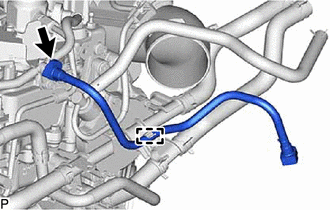
Disengage the clamp.
Remove the fuel tube sub-assembly from the fuel pipe sub-assembly.
Click hereEngine / Hybrid System>G16E-GTS (FUEL)>FUEL SYSTEM>PRECAUTION
87245
3.REMOVE HEATER WATER HOSE INLET
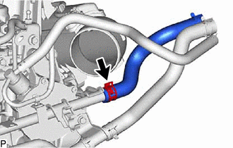
Slide the clip and remove the heater water hose inlet from the No. 1 water by-pass pipe.
87246
4.REMOVE HEATER WATER HOSE OUTLET
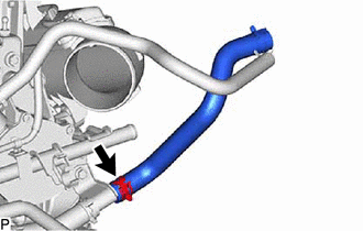
Slide the clip and remove the heater water hose outlet from the No. 3 water by-pass pipe.
17342D
5.REMOVE NO. 2 AIR HOSE
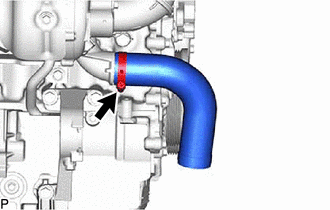
Loosen the hose clamp and remove the No. 2 air hose from the turbocharger sub-assembly.
17345F
6.REMOVE NO. 5 AIR HOSE
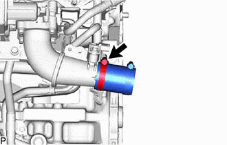
Loosen the hose clamp and remove the No. 5 air hose from the air tube assembly.
16283
7.REMOVE NO. 6 WATER BY-PASS HOSE
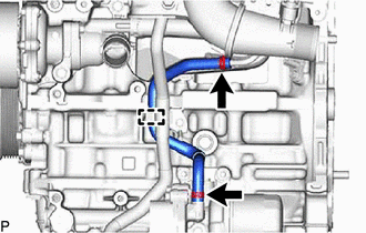
Slide the 2 clips and separate the No. 6 water by-pass hose.
Disengage the clamp and remove the No. 6 water by-pass hose from the No. 1 water hose clamp bracket.
16282
8.REMOVE NO. 5 WATER BY-PASS HOSE
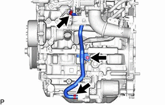
Slide the 2 clips and separate the No. 5 water by-pass hose.
Remove the bolt and No. 5 water by-pass hose from the crankshaft bearing cap assembly.
25781A
9.REMOVE NO. 3 VACUUM TRANSMITTING HOSE
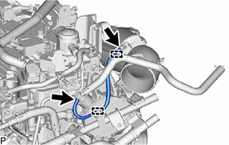
Disengage the 2 clamp and remove the No. 3 vacuum transmitting hose.
44774
10.REMOVE UNION TO CONNECTOR TUBE HOSE
16284
11.REMOVE NO. 1 TURBO WATER HOSE
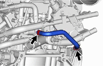
Slide the 2 clips and remove the No. 1 turbo water hose.
16268
12.REMOVE NO. 1 WATER BY-PASS PIPE
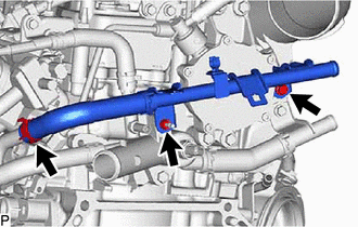
Slide the clip and separate the water by-pass hose.
Remove the bolt, nut and No. 1 water by-pass pipe.
16279
13.REMOVE NO. 3 WATER BY-PASS PIPE
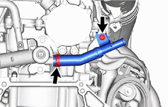
Remove the bolt and separate the No. 3 water by-pass pipe.
Slide the clip and remove the No. 3 water by-pass pipe.
16288
14.REMOVE NO. 4 WATER BY-PASS PIPE
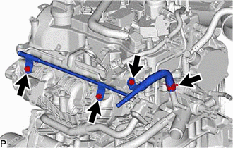
Remove the 3 bolts and separate the No. 4 water by-pass pipe.
Slide the clip and remove the No. 4 water by-pass pipe.
15.REMOVE WATER BY-PASS HOSE ASSEMBLY
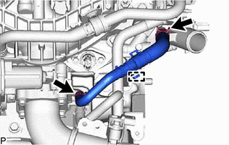
Disengage the clamp.
Slide the 2 clips and remove the water by-pass hose assembly.
89421
16.REMOVE E.F.I. VACUUM SENSOR ASSEMBLY
89481B
17.REMOVE DIFFERENTIAL PRESSURE SENSOR (w/ Differential Pressure Sensor)
18.REMOVE INTAKE AIR PIPE
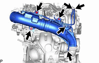
Separate the No.1 vaccum transmitting hose.
Separate the No. 2 vaccum transmitting hose.
Separate the ventilation hose.
Remove the e3 bolts.
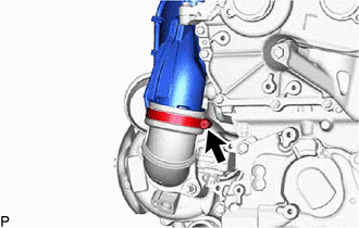
Loosen the hose clamp and remove the intake air pipe from the .
12285A
19.REMOVE ENGINE HANGER BRACKET
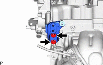
Remove the 2 bolts and engine hanger bracket from the cylinder head sub-assembly.
43457
20.REMOVE DRIVE SHAFT BEARING BRACKET
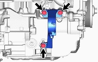
Remove the 3 bolts and drive shaft bearing bracket from the cylinder block sub-aseembly.
12584
21.REMOVE NO. 4 CYLINDER BROCK INSULATOR
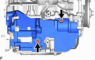
Remove the 2 bolts and No. 4 cylinder brock insulator.
17271
22.REMOVE NO. 1 TURBO INSULATOR
17201
23.REMOVE TURBOCHARGER SUB-ASSEMBLY
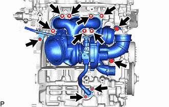
Remove the 2 bolts and separate the outlet turbo oil pipe.
Remove the inlet turbo oil pipe union bolt.
Remove the 2 bolts and separate the No. 1 turbo water pipe sub-assembly.
Remove the 7 nuts and turbocharger sub-aseembly from the cylinder head sub-aseembly.
17272
24.REMOVE NO. 2 TURBO INSULATOR
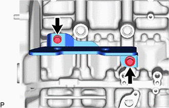
Remove the 2 bolts and No. 2 turbo insulator from the cylinder brock sub-assembly.
25860
25.REMOVE PURGE VALVE (PURGE VSV)
82126A
26.REMOVE NO. 6 ENGINE WIRE
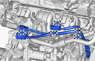
Disengage the 5 clamps and separate the No. 6 engine wire.
12632A
27.REMOVE NO. 2 ENGINE COVER BRACKET
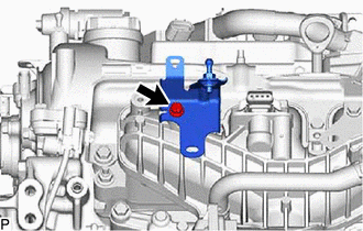
Remove the bolt and No. 2 engine cover bracket from the intake manifold.
17872
28.REMOVE INTAKE AIR CONNECTOR BRACKET
17111
29.REMOVE INTAKE MANIFOLD
30.REMOVE WATER BY-PASS PIPE
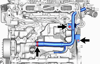
Remove the bolt and nut.
Slide the clip and remove the water by-pass pipe from the water inlet with thermostat sub-assembly.
82127D
31.REMOVE NO. 7 ENGINE WIRE
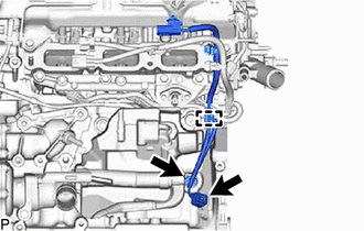
Disengage the clamp.
Disconnect the 2 connectors and remove the No. 7 engine wire.
23902
32.REMOVE FUEL TUBE SUB-ASSEMBLY
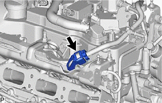
Remove the fuel pipe clamp from the fuel tube connector.
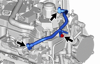
Remove the bolt.
Remove the fuel tube sub-assembly.
Click hereEngine / Hybrid System>G16E-GTS (FUEL)>FUEL SYSTEM>PRECAUTION
15301B
33.REMOVE OIL LEVEL GAGE SUB-ASSEMBLY
11452D
34.REMOVE OIL LEVEL GAGE GUIDE
23825
35.REMOVE FUEL DELIVERY GUARD
23807V
36.REMOVE NO. 1 DELIVERY PIPE SPACER
Remove the No. 1 delivery pipe spacer.
23814B
37.REMOVE FUEL DELIVERY PIPE (for Low Pressure)
23891
38.REMOVE FUEL DELIVERY SPACER
23291
39.REMOVE INJECTOR VIBRATION INSULATOR
23801P
40.REMOVE NO. 1 FUEL PIPE SUB-ASSEMBLY
23100X
41.REMOVE FUEL PUMP ASSEMBLY (ENGINE ROOM SIDE)
12218
42.REMOVE NO. 1 VENTILATION FLANGE SEPARATOR
23807
43.REMOVE FUEL DELIVERY PIPE SUB-ASSEMBLY (for High Pressure)
82126A
44.REMOVE NO. 6 ENGINE WIRE
23250E
45.REMOVE DIRECT FUEL INJECTOR ASSEMBLY
23255A
46.REMOVE FUEL INJECTOR SEAL
12582D
47.REMOVE NO. 2 CYLINDER BLOCK INSULATOR
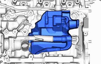
Remove the No. 2 cylinder block insulator from the cylinder block sub-assembly.
82219A
48.REMOVE SENSOR WIRE
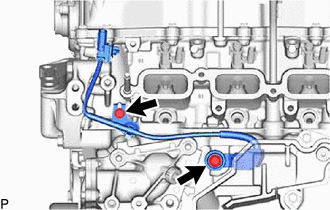
Remove the 2 bolts and remove the sensor wire from the cylinder block sub-assembly.
12261
49.REMOVE VENTILATION HOSE
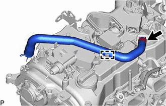
Disengage the clamp.
Slide the clip and remove the ventilation hose from the cylinder head cover sub-assembly.
25819
50.REMOVE VACUUM REGULATING VALVE ASSEMBLY
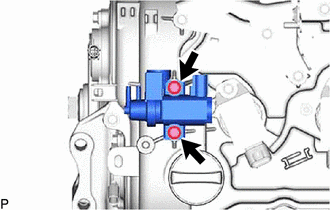
Remove the 2 bolts and vacuum regulating valve assembly from the cylinder head cover sub-assembly.
19500
51.REMOVE IGNITION COIL ASSEMBLY
52.REMOVE ENGINE COVER JOINT
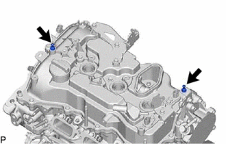
Remove the 2 engine cover joints from the cylinder head cover sub-assembly.
12631A
53.REMOVE ENGINE COVER BRACKET
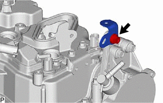
Remove the bolt and engine cover bracket from the No. 1 vacuum pump bracket.
23881B
54.REMOVE FUEL HOSE BRACKET
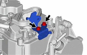
Remove the 2 bolts and fuel hose bracket form the cylinder head cover sub-assembly.
17138
55.REMOVE INTAKE PIPE OR HOSE STAY
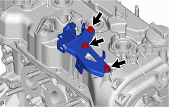
Remove the 3 bolts and intake pipe or hose stay from the cylinder head cover sub-assembly.
12583A
56.REMOVE NO. 3 CYLINDER BLOCK INSULATOR
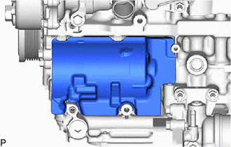
Remove the No. 3 cylinder block insulator from the cylinder block sub-assembly.
11336A
57.REMOVE TIMING GEAR COVER INSULATOR
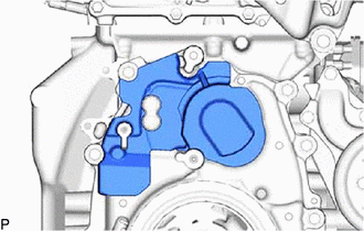
Remove the timing gear cover insulator from the timing chain cover assembly.