G16E-GTS INTAKE / EXHAUST TURBOCHARGER INSTALLATION
PROCEDURE

 1.INSTALL STUD BOLT
Using an E8 "TORX" socket wrench, install the stud bolt to the turbocharger sub-assembly.
- Torque:
- 10 N*m (102 kgf*cm, 7 ft.*lbf)
16347A
2.INSTALL TURBO WATER PIPE GASKET
Install the new turbo water pipe gascket to the turbocharger sub-assembly.
16027
3.INSTALL NO. 1 TURBO WATER PIPE SUB-ASSEMBLY
Install the No. 1 turbo water pipe sub-assembly to the turbocharger sub-assembly with the 2 bolts.
- Torque:
- 10 N*m (102 kgf*cm, 7 ft.*lbf)
15407
4.CONNECT TURBO OIL INLET PIPE SUB-ASSEMBLY
Install a new gasket to the turbo water pipe sub-assembly.
Install the turbo water pipe sub-assembly to the turbocharger sub-assembly with the bolt.
- Torque:
- 35 N*m (357 kgf*cm, 26 ft.*lbf)
17274
5.CONNECT COMPRESSOR INLET ELBOW
Install a new gasket to the compressor inlet elbow.
Install the compressor inlet elbow to the turbocharger sub-assembly with the bolt and nut.
- Torque:
- 21 N*m (214 kgf*cm, 15 ft.*lbf)
6.INSTALL STUD BOLT
17173
7.INSTALL EXHAUST MANIFOLD TO HEAD GASKET
Install a new exhaust manifold to head gasket to the cylinder head sub-assembly.
17201
8.INSTALL TURBOCHARGER SUB-ASSEMBLY
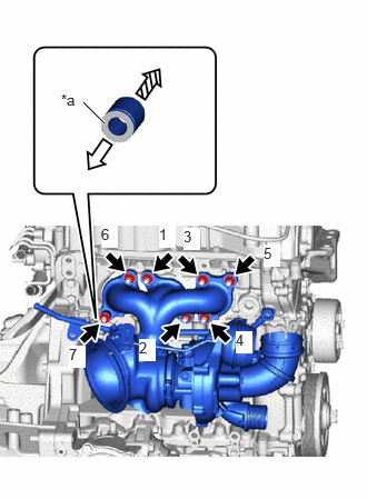
| *a | Color(Red) |

|
Rear Side |

|
Front Side |
Install the collar to the turbocharger sub-assembly with the red side facing the rear of the vehicle.
Tighten the 7 nuts in the order shown in the illustration.
- Torque:
- 44.3 N*m (452 kgf*cm, 33 ft.*lbf)
9.CONNECT WIRE HARNESS
Connect the connector to the turbocharger sub-assembly.
16027
10.CONNECT NO. 1 TURBO WATER PIPE SUB-ASSEMBLY
Install a new gasket to the inlet No. 1 turbo water pipe sub-assembly.
Install the No. 1 turbo water pipe sub-assembly to the cylinder block sub-assembly with the bolt and union bolt.
- Torque:
- Bolt : 13 N*m (133 kgf*cm, 10 ft.*lbf)
- Union Bolt : 35 N*m (357 kgf*cm, 26 ft.*lbf)
Connect the turbo water hose to the No. 1 turbo water pipe sub-assembly and slide the clip to secure it.
15407A
11.INSTALL TURBO OIL INLET PIPE UNION BOLT
Install a new gasket to the inlet turbo oil pipe sub-assembly.
Install the inlet turbo oil pipe sub-assembly to the cylinder block sub-assembly with the union bolt.
- Torque:
- 35 N*m (357 kgf*cm, 26 ft.*lbf)
25771B
12.INSTALL NO. 2 VACUUM TRANSMITTING HOSE
Connect the No. 2 vaccum transmitting hose.
17342D
13.INSTALL NO. 2 AIR HOSE
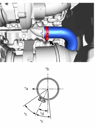
| *a | Right of Vehicle |
| *b | Top of Vehicle |
| *c | 30° |
| *d | 25° |
Install the new No. 2 air hose to the turbocharger sub-assembly and tighten the hose clamp.
- Torque:
- 6.0 N*m (61 kgf*cm, 53 in.*lbf)
15474
14.CONNECT TURBO OIL OUTLET PIPE
Install a new gasket to the outlet turbo oil pipe.
Install the outlet turbo oil pipe to the turbocharger sub-assembly with the 2 bolts.
- Torque:
- 10 N*m (102 kgf*cm, 7 ft.*lbf)
17271
15.INSTALL NO. 1 TURBO INSULATOR
Install the No. 1 turbo insulator to the turbocharger sub-assembly with the 3 bolts.
- Torque:
- 21 N*m (214 kgf*cm, 15 ft.*lbf)
17311A
16.INSTALL NO. 1 AIR INLET DUCT
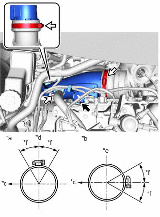
| *a | Upper Side |
| *b | Lower Side |
| *c | Rear of Vehicle |
| *d | Top of Vehicle |
| *e | Left of Vehicle |
| *f | 30° |
Install the No. 1 air inlet duct to the compressor inlet elbow and tighten the hose clamp.
- Torque:
- 3.0 N*m (31 kgf*cm, 27 in.*lbf)
Install the No. 1 air inlet duct to the No. 1 air hose and tighten the hose clamp.
- Torque:
- 4.0 N*m (41 kgf*cm, 35 in.*lbf)
Install the No. 1 air inlet duct to the cylinder head sub-assembly with the bolt.
- Torque:
- 10 N*m (102 kgf*cm, 7 ft.*lbf)
Connect the ventilation hose to the No. 1 air inlet duct and slide the clip to secure it.
17893
17.INSTALL INTAKE AIR RESONATOR
Install the intake air resonator to the No. 1 air hose and tighten the hose clamp.
- Torque:
- 3.0 N*m (31 kgf*cm, 27 in.*lbf)
Install the intake air resonator to the air cleaner hose assembly and tighten the hose clamp.
- Torque:
- 3.0 N*m (31 kgf*cm, 27 in.*lbf)
Install the intake air resonator to the cylinder head sub-assembly with the 2 bolts.
- Torque:
- 21 N*m (214 kgf*cm, 15 ft.*lbf)
18.INSTALL AIR CLEANER CASE SUB-ASSEMBLY
Engage the 3 grommets and pin to install the air cleaner case sub-assembly.
Engage the 6 clamps.
Connect the 3 connector.
17881
19.CONNECT NO. 1 AIR CLEANER HOSE
Connect the No. 1 air cleaner hose to the air cleaner case sub-assembly and tighten the hose clamp.
- Torque:
- 3.0 N*m (31 kgf*cm, 27 in.*lbf)
17751
20.INSTALL NO. 1 AIR CLEANER INLET
Install the No.1 air cleaner inlet with 2 clips
55225
21.INSTALL DASH PANEL HEAT INSULATOR
Install the dash panel heat insulator to the vehicle body with the 3 nuts and clamp.
- Torque:
- 5.0 N*m (51 kgf*cm, 44 in.*lbf)
55701J
22.INSTALL OUTER COWL TOP PANEL SUB-ASSEMBLY (for RHD)
55701J
23.INSTALL OUTER COWL TOP PANEL SUB-ASSEMBLY (for LHD)
55815E
24.INSTALL NO. 1 FRONT VENTILATOR SEAL (for RHD)
55815E
25.INSTALL NO. 1 FRONT VENTILATOR SEAL (for LHD)
55735A
26.INSTALL WATER GUARD PLATE LH (for RHD)
55734A
27.INSTALL WATER GUARD PLATE RH (for LHD)
28.INSTALL WINDSHIELD WIPER MOTOR AND LINK
25051
29.INSTALL EXHAUST MANIFOLD CONVERTER SUB-ASSEMBLY
30.ADD ENGINE COOLANT
31.INSPECT FOR COOLANT LEAK
32.ADD ENGINE OIL
33.CHECK ENGINE OIL LEVEL
34.INSPECT FOR ENGINE OIL LEAK
35.CHECK ENGINE OIL LEVEL