AUDIO / VIDEO AUDIO AND VISUAL SYSTEM(for Radio and Display Type with TAS Type) Lost Communication with Local Bus
WIRING DIAGRAM
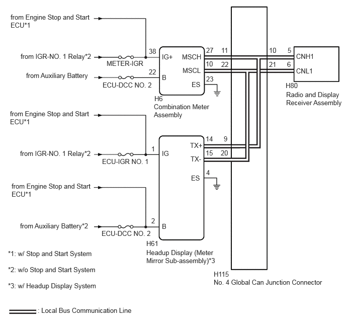
CAUTION / NOTICE / HINT
- NOTICE:
-
Inspect the fuses for circuits related to this system before performing the following procedure.
PROCEDURE
Check for color of status indicators.
- Result:
Result Proceed to MM-SUB-BUS communication indicator is green A MM-SUB-BUS communication indicator is red B
A
Click hereGeneral>INTRODUCTION>HOW TO TROUBLESHOOT ECU CONTROLLED SYSTEMS>HOW TO PROCEED WITH TROUBLESHOOTING
B
Check the vehicle type.
- Result:
Result Proceed to w/o Stop and Start System A w/ Stop and Start System B
A
B
Disconnect the H6 combination meter assembly connector.
Measure the resistance according to the value(s) in the table below.
- Standard Resistance:
Tester Connection Condition Specified Condition H6-23 (ES) - Body ground Always Below 1 Ω
Measure the voltage according to the value(s) in the table below.
- Standard Voltage:
Tester Connection Switch Condition Specified Condition H6-22 (B) - Body ground Ignition switch off 11 to 14 V H6-38 (IG+) - Body ground Ignition switch ON 11 to 14 V
- Result:
Proceed to OK NG
OK
NG
Check the vehicle type.
- Result:
Result Proceed to w/o Headup Display System A w/ Headup Display System B
A
B
Disconnect the cable from the negative (-) auxiliary battery terminal.
Disconnect the H115 No. 4 global can junction connector.
Connect the H6 combination meter assembly connector.
Measure the resistance according to the value(s) in the table below.
- Standard Resistance:
Tester Connection Condition Specified Condition H115-11 - H115-22 Cable disconnected from negative (-) auxiliary battery terminal 108 to 132 Ω
- Result:
Proceed to OK NG
OK
NG
Disconnect the cable from the negative (-) auxiliary battery terminal.
Disconnect the H115 No. 4 global can junction connector.
Connect the H80 radio and display receiver assembly connector.
Measure the resistance according to the value(s) in the table below.
- Standard Resistance:
Tester Connection Condition Specified Condition H115-10 - H115-21 Cable disconnected from negative (-) auxiliary battery terminal 108 to 132 Ω
- Result:
Proceed to OK NG
OK
NG
Disconnect the cable from the negative (-) auxiliary battery terminal.
Disconnect the H80 radio and display receiver assembly connector.
Connect the H6 combination meter assembly connector.
Connect the H115 No. 4 global can junction connector.
Measure the resistance according to the value(s) in the table below.
- Standard Resistance:
Tester Connection Condition Specified Condition H80-5 (CNH1) - H80-6 (CNL1) Cable disconnected from negative (-) auxiliary battery terminal 108 to 132 Ω
- Result:
Proceed to OK NG
OK
NG
Disconnect the cable from the negative (-) auxiliary battery terminal.
Disconnect the H6 combination meter assembly connector.
Connect the H80 radio and display receiver assembly connector.
Connect the H115 No. 4 global can junction connector.
Measure the resistance according to the value(s) in the table below.
- Standard Resistance:
Tester Connection Condition Specified Condition H6-27 (MSCH) - H6-10 (MSCL) Cable disconnected from negative (-) auxiliary battery terminal 108 to 132 Ω
- Result:
Proceed to OK NG
OK
NG
Disconnect the H61 headup display (meter mirror sub-assembly) connector.
Measure the resistance according to the value(s) in the table below.
- Standard Resistance:
Tester Connection Condition Specified Condition H61-4 (ES) - Body ground Always Below 1 Ω
Measure the voltage according to the value(s) in the table below.
- Standard Voltage:
Tester Connection Switch Condition Specified Condition H61-2 (B) - Body ground Ignition switch off 11 to 14 V H61-1 (IG) - Body ground Ignition switch ON 11 to 14 V
- Result:
Proceed to OK NG
OK
NG
Disconnect the cable from the negative (-) auxiliary battery terminal.
Disconnect the H115 No. 4 global can junction connector.
Connect the H6 combination meter assembly connector.
Measure the resistance according to the value(s) in the table below.
- Standard Resistance:
Tester Connection Condition Specified Condition H115-11 - H115-22 Cable disconnected from negative (-) auxiliary battery terminal 108 to 132 Ω
- Result:
Proceed to OK NG
OK
NG
Disconnect the cable from the negative (-) auxiliary battery terminal.
Disconnect the H115 No. 4 global can junction connector.
Connect the H80 radio and display receiver assembly connector.
Measure the resistance according to the value(s) in the table below.
- Standard Resistance:
Tester Connection Condition Specified Condition H115-10 - H115-21 Cable disconnected from negative (-) auxiliary battery terminal 108 to 132 Ω
- Result:
Proceed to OK NG
OK
NG
Disconnect the cable from the negative (-) auxiliary battery terminal.
Disconnect the H115 No. 4 global can junction connector.
Connect the H61 headup display (meter mirror sub-assembly) connector.
Measure the resistance according to the value(s) in the table below.
- Standard Resistance:
Tester Connection Condition Specified Condition H115-9 - H115-20 Cable disconnected from negative (-) auxiliary battery terminal 200 Ω or higher
- Result:
Proceed to OK NG
OK
NG
Disconnect the cable from the negative (-) auxiliary battery terminal.
Disconnect the H6 combination meter assembly connector.
Disconnect the H61 headup display (meter mirror sub-assembly) connector.
Connect the H80 radio and display receiver assembly connector.
Connect the H115 No. 4 global can junction connector.
Measure the resistance according to the value(s) in the table below.
- Standard Resistance:
Tester Connection Condition Specified Condition H61-14 (TX+) - H61-15 (TX-) Cable disconnected from negative (-) auxiliary battery terminal 108 to 132 Ω
- Result:
Proceed to OK NG
OK
NG
Disconnect the cable from the negative (-) auxiliary battery terminal.
Disconnect the H80 radio and display receiver assembly connector.
Disconnect the H61 headup display (meter mirror sub-assembly) connector.
Connect the H6 combination meter assembly connector.
Connect the H115 No. 4 global can junction connector.
Measure the resistance according to the value(s) in the table below.
- Standard Resistance:
Tester Connection Condition Specified Condition H80-5 (CNH1) - H80-6 (CNL1) Cable disconnected from negative (-) auxiliary battery terminal 108 to 132 Ω
- Result:
Proceed to OK NG
OK
NG
Disconnect the cable from the negative (-) auxiliary battery terminal.
Disconnect the H6 combination meter assembly connector.
Disconnect the H61 headup display (meter mirror sub-assembly) connector.
Connect the H80 radio and display receiver assembly connector.
Connect the H115 No. 4 global can junction connector.
Measure the resistance according to the value(s) in the table below.
- Standard Resistance:
Tester Connection Condition Specified Condition H6-27 (MSCH) - H6-10 (MSCL) Cable disconnected from negative (-) auxiliary battery terminal 108 to 132 Ω
- Result:
Proceed to OK NG
OK
NG
Disconnect the H6 combination meter assembly connector.
Measure the resistance according to the value(s) in the table below.
- Standard Resistance:
Tester Connection Condition Specified Condition H6-23 (ES) - Body ground Always Below 1 Ω
Measure the voltage according to the value(s) in the table below.
- Standard Voltage:
Tester Connection Switch Condition Specified Condition H6-22 (B) - Body ground Ignition switch off 11 to 14 V H6-38 (IG+) - Body ground Ignition switch ON 10.5 to 16 V
- Result:
Proceed to OK NG
OK
NG
Check the vehicle type.
- Result:
Result Proceed to w/o Headup Display System A w/ Headup Display System B
A
B
Disconnect the cable from the negative (-) auxiliary battery terminal.
Disconnect the H115 No. 4 global can junction connector.
Connect the H6 combination meter assembly connector.
Measure the resistance according to the value(s) in the table below.
- Standard Resistance:
Tester Connection Condition Specified Condition H115-11 - H115-22 Cable disconnected from negative (-) auxiliary battery terminal 108 to 132 Ω
- Result:
Proceed to OK NG
OK
NG
Disconnect the cable from the negative (-) auxiliary battery terminal.
Disconnect the H115 No. 4 global can junction connector.
Connect the H80 radio and display receiver assembly connector.
Measure the resistance according to the value(s) in the table below.
- Standard Resistance:
Tester Connection Condition Specified Condition H115-10 - H115-21 Cable disconnected from negative (-) auxiliary battery terminal 108 to 132 Ω
- Result:
Proceed to OK NG
OK
NG
Disconnect the cable from the negative (-) auxiliary battery terminal.
Disconnect the H80 radio and display receiver assembly connector.
Connect the H6 combination meter assembly connector.
Connect the H115 No. 4 global can junction connector.
Measure the resistance according to the value(s) in the table below.
- Standard Resistance:
Tester Connection Condition Specified Condition H80-5 (CNH1) - H80-6 (CNL1) Cable disconnected from negative (-) auxiliary battery terminal 108 to 132 Ω
- Result:
Proceed to OK NG
OK
NG
Disconnect the cable from the negative (-) auxiliary battery terminal.
Disconnect the H6 combination meter assembly connector.
Connect the H80 radio and display receiver assembly connector.
Connect the H115 No. 4 global can junction connector.
Measure the resistance according to the value(s) in the table below.
- Standard Resistance:
Tester Connection Condition Specified Condition H6-27 (MSCH) - H6-10 (MSCL) Cable disconnected from negative (-) auxiliary battery terminal 108 to 132 Ω
- Result:
Proceed to OK NG
OK
NG
Disconnect the H61 headup display (meter mirror sub-assembly) connector.
Measure the resistance according to the value(s) in the table below.
- Standard Resistance:
Tester Connection Condition Specified Condition H61-4 (ES) - Body ground Always Below 1 Ω
Measure the voltage according to the value(s) in the table below.
- Standard Voltage:
Tester Connection Switch Condition Specified Condition H61-2 (B) - Body ground Ignition switch off 11 to 14 V H61-1 (IG) - Body ground Ignition switch ON 10.5 to 16 V
- Result:
Proceed to OK NG
OK
NG
Disconnect the cable from the negative (-) auxiliary battery terminal.
Disconnect the H115 No. 4 global can junction connector.
Connect the H6 combination meter assembly connector.
Measure the resistance according to the value(s) in the table below.
- Standard Resistance:
Tester Connection Condition Specified Condition H115-11 - H115-22 Cable disconnected from negative (-) auxiliary battery terminal 108 to 132 Ω
- Result:
Proceed to OK NG
OK
NG
Disconnect the cable from the negative (-) auxiliary battery terminal.
Disconnect the H115 No. 4 global can junction connector.
Connect the H80 radio and display receiver assembly connector.
Measure the resistance according to the value(s) in the table below.
- Standard Resistance:
Tester Connection Condition Specified Condition H115-10 - H115-21 Cable disconnected from negative (-) auxiliary battery terminal 108 to 132 Ω
- Result:
Proceed to OK NG
OK
NG
Disconnect the cable from the negative (-) auxiliary battery terminal.
Disconnect the H115 No. 4 global can junction connector.
Connect the H61 headup display (meter mirror sub-assembly) connector.
Measure the resistance according to the value(s) in the table below.
- Standard Resistance:
Tester Connection Condition Specified Condition H115-9 - H115-20 Cable disconnected from negative (-) auxiliary battery terminal 200 Ω or higher
- Result:
Proceed to OK NG
OK
NG
Disconnect the cable from the negative (-) auxiliary battery terminal.
Disconnect the H6 combination meter assembly connector.
Disconnect the H61 headup display (meter mirror sub-assembly) connector.
Connect the H80 radio and display receiver assembly connector.
Connect the H115 No. 4 global can junction connector.
Measure the resistance according to the value(s) in the table below.
- Standard Resistance:
Tester Connection Condition Specified Condition H61-14 (TX+) - H61-15 (TX-) Cable disconnected from negative (-) auxiliary battery terminal 108 to 132 Ω
- Result:
Proceed to OK NG
OK
NG
Disconnect the cable from the negative (-) auxiliary battery terminal.
Disconnect the H80 radio and display receiver assembly connector.
Disconnect the H61 headup display (meter mirror sub-assembly) connector.
Connect the H6 combination meter assembly connector.
Connect the H115 No. 4 global can junction connector.
Measure the resistance according to the value(s) in the table below.
- Standard Resistance:
Tester Connection Condition Specified Condition H80-5 (CNH1) - H80-6 (CNL1) Cable disconnected from negative (-) auxiliary battery terminal 108 to 132 Ω
- Result:
Proceed to OK NG
OK
NG
Disconnect the cable from the negative (-) auxiliary battery terminal.
Disconnect the H6 combination meter assembly connector.
Disconnect the H61 headup display (meter mirror sub-assembly) connector.
Connect the H80 radio and display receiver assembly connector.
Connect the H115 No. 4 global can junction connector.
Measure the resistance according to the value(s) in the table below.
- Standard Resistance:
Tester Connection Condition Specified Condition H6-27 (MSCH) - H6-10 (MSCL) Cable disconnected from negative (-) auxiliary battery terminal 108 to 132 Ω
- Result:
Proceed to OK NG
OK
NG