Brake Warning Light Remains ON
Circuit diagnosis · Vehicles built from Aug 2005
DESCRIPTION
If any of the following conditions are detected, the BRAKE warning light remains on:- The ECU connectors are disconnected from the skid control ECU.
- The brake fluid level is insufficient.
- The parking brake is applied.
- The EBD is defective.
WIRING DIAGRAM
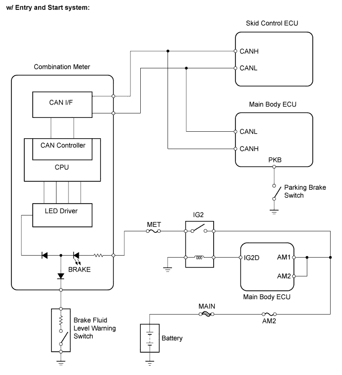

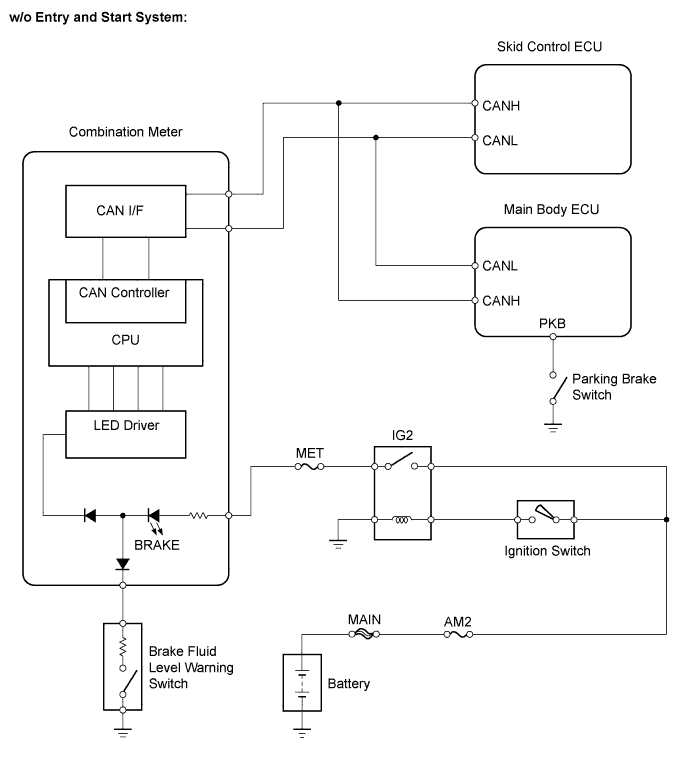
INSPECTION PROCEDURE
| 1. PREPARE FOR INSPECTION |

Check that both of the following conditions are satisfied.
- The brake fluid level in the brake master cylinder reservoir is correct.
- The parking brake is released.
- HINT:
- When the ABS warning light remains illuminated, repair the malfunctions in the ABS system first.
- The brake fluid level in the brake master cylinder reservoir is correct.
| NEXT | |
 |
| 2. CHECK DTC |
Check if any ABS DTCs are output (Click here).
Result
Proceed to
DTC not output
A
DTC output
B
|
|
||||

| A | |
|
| 3. CHECK CAN COMMUNICATION SYSTEM |
Check if the CAN communication system DTC is output (Click here).
Result
Proceed to
DTC not output
A
DTC output
B
|
|
||||
| A | |
|
| 4. CHECK CONNECTOR CONNECTION CONDITION |
Check if the skid control ECU connector is connected securely.
- OK:
- The connector is connected securely.
|
|
||||
| OK | |
|
| 5. CHECK PARKING BRAKE SWITCH ASSEMBLY |
Connect the intelligent tester to the DLC3.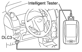
Turn the ignition switch on (IG).
Turn the tester on.
Select the "Parking Brake SW" in the DATA LIST.Select the following menu items: Chassis / ABS/VSC/TRC / Data List.
DATA LIST: ABS/VSC/TRC Item (Display)
Measurement Item / Range (Display)
Normal Condition
Parking Brake SW
Parking brake switch / ON or OFF
ON: Parking brake applied
OFF: Parking brake released
Check that "ON" and "OFF" are properly indicated on the tester display when the parking brake lever is operated.
- OK:
- Tester display changes in accordance with the parking brake lever operation.
|
|
||||

| OK | |
|
| 6. INSPECT BRAKE FLUID LEVEL WARNING SWITCH |
Remove the reservoir tank cap and strainer.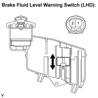
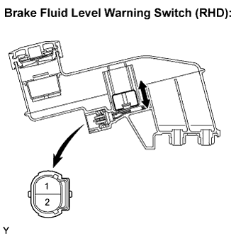
Disconnect the brake fluid level warning switch connector.
Measure the resistance.
- HINT:
- A float is placed inside the reservoir. Its position can be changed by increasing or decreasing the brake fluid level.
- Standard Resistance:
Tester Connection
Condition
Specified Condition
1 - 2
Float up (Switch OFF)
10 kΩ or higher
1 - 2
Float down (Switch ON)
Below 1 Ω
- HINT:
- If there is no problem after the above check is finished, adjust the brake fluid level to the MAX level.
|
|
||||
| OK | |
|
| 7. CHECK HARNESS AND CONNECTOR (COMBINATION METER - BRAKE FLUID LEVEL WARNING SWITCH) |
Disconnect the D2 combination meter connector.
Disconnect the brake fluid level warning switch connector.
Measure the resistance.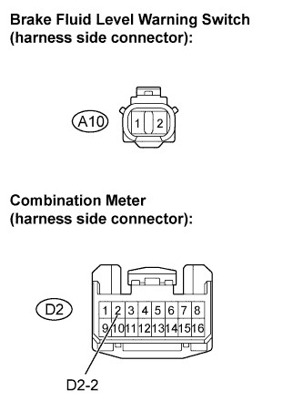
- Standard Resistance:
Tester Connection
Specified Condition
D2-2 - J10-1
Below 1 Ω
D2-2 - Body ground
10 kΩ or higher
A10-2 - Body ground
10 kΩ or higher
|
|
||||
| OK | |
|
| 8. INSPECT COMBINATION METER |
Inspect the combination meter (Click here).
|
|
||||
| OK | ||
 |
||
| ||
| 9. INSPECT PARKING BRAKE SWITCH ASSEMBLY |
Disconnect the parking brake switch connector.
Measure the resistance.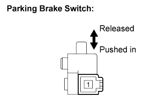
- Standard Resistance:
Tester Connection
Condition
Specified Condition
1 - Body ground
Parking brake switch ON
(Switch pin released)
Below 1 Ω
1 - Body ground
Parking brake switch OFF
(Switch pin pushed in)
10 kΩ or higher
|
|
||||
| OK | |
|
| 10. CHECK HARNESS AND CONNECTOR (MAIN BODY ECU - PARKING BRAKE SWITCH ASSEMBLY) |
Disconnect connector 4C of the main body ECU (Click here).
Disconnect the parking brake switch connector.
Measure the resistance.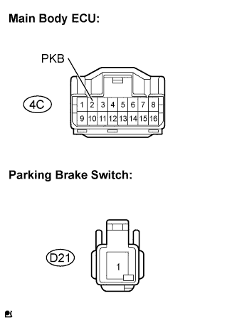
- Standard Resistance:
Tester Connection
Specified Condition
4C-2 (PKB) - D21-1
Below 1 Ω
4C-2 (PKB) - Body ground
10 kΩ or higher
|
|
||||
| OK | ||
|
||
| ||