P0340 Camshaft Position Sensor "A" Circuit (Bank 1 or Single Sensor)
Diagnostic trouble codes · Vehicles built from Nov 2005
DESCRIPTION
The Camshaft Position (CMP) sensor installed on the cylinder head. The sensor plate has one tooth on its circumference, and is installed on the camshaft timing pulley. When the camshaft rotates, the tooth on the camshaft timing pulley passes through the CMP sensor. The generated voltage in the sensor acts as a signal. The ECM locates each cylinder position based on the combination of this signal and crankshaft position sensor output.| DTC No. |
DTC Detection Conditions |
Trouble Areas |
| P0340 |
No camshaft position sensor signal to ECM while cranking (The MIL is illuminated and a DTC is immediately set when a malfunction is detected) |
|
- HINT:
- DTC P0340 is detected when the engine cranks 5 revolutions or more and also detected when idling.
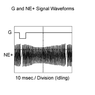

- HINT:
- The correct waveform is as shown on the left.
- G stands for the camshaft position sensor signal, and NE+ stands for the crankshaft position sensor signal.
- Grounding failure of the shielded wire may cause noise in waveforms.
- The correct waveform is as shown on the left.
Item
Contents
Terminal
CH1: G1 - EG
CH2: NE+ - NE-
Equipment Setting
10 ms/Division
Condition
While cranking or idling
WIRING DIAGRAM
Refer to DTC P0335 (Click here).INSPECTION PROCEDURE
- HINT:
- Read freeze frame data using an intelligent tester. Freeze frame data record the engine condition when malfunctions are detected. When troubleshooting, freeze frame data can help determine if the vehicle was moving or stationary, if the engine was warmed up or not, if the air-fuel ratio was lean or rich, and other data, from the time the malfunction occurred.
| 1. INSPECT CAMSHAFT POSITION SENSOR (POWER SOURCE VOLTAGE) |

Disconnect the C49 camshaft position sensor connector.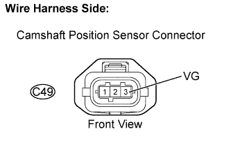
Turn the ignition switch on (IG).
Measure the voltage between the terminal of the wire harness side connector and body ground.
- Standard voltage:
Tester Connections
Specified Conditions
VG (C49-3) - Body ground
9 to 14 V
Reconnect the camshaft position sensor connector.
|
|
||||

| OK | |
 |
| 2. CHECK HARNESS AND CONNECTOR (CAMSHAFT POSITION SENSOR - ECM) |
Disconnect the C49 camshaft position sensor connector.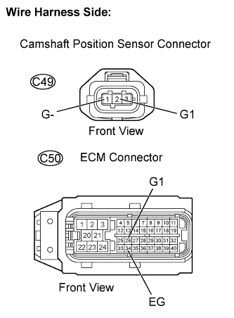
Disconnect the C50 ECM connector.
Check the resistance.
- Standard resistance (Check for open):
Tester Connections
Specified Conditions
G1 (C49-2) - G1 (C50-26)
Below 1 Ω
G- (C49-1) - EG (C50-34)
- Standard (Check for short):
Tester Connections
Specified Conditions
G1 (C49-2) or G1 (C50-26) - Body ground
10 kΩ or higher
G- (C49-1) or EG (C50-34) - Body ground
Reconnect the camshaft position sensor connector.
Reconnect the ECM connector.
|
|
||||

| OK | |
|
| 3. CHECK SENSOR INSTALLATION (CAMSHAFT POSITION SENSOR) |
Check the camshaft position sensor installation.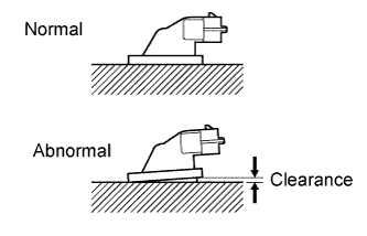
- OK:
- Sensor is installed correctly.
|
|
||||
| OK | |
|
| 4. CHECK VALVE TIMING |
Remove the cylinder head cover (Click here).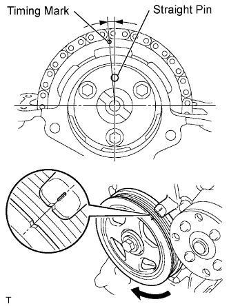
Turn the crankshaft pulley until the grooves of the crankshaft damper and oil pump are aligned.
Check that the timing mark of the camshaft timing sprocket and the straight pin hole of the crankshaft timing sprocket are in the positions shown in the illustration.If not, turn the crankshaft 1 revolution (360°), then align the marks as above.
- OK:
- Timing marks on camshaft timing gears are aligned as shown in the illustration.
Reinstall the cylinder head cover (Click here).
|
|
||||
| OK | |
|
| 5. CHECK CAMSHAFT TIMING GEAR OR SPROCKET |
Check the teeth of the camshaft timing gear or sprocket.
- OK:
- The teeth do not have any cracks or deformation.
|
|
||||
| OK | |
|
| 6. REPLACE CAMSHAFT POSITION SENSOR |
| NEXT | |
|
| 7. CHECK WHETHER DTC OUTPUT RECURS (DTCS P0340) |
Connect an intelligent tester to the DLC3.
Turn the ignition switch on (IG) and turn the tester on.
Clear DTCs (Click here).
Start the engine.
Select the following menu item: Powertrain / Engine and ECT / DTC.
Read DTCs.
- Result:
Display (DTC Output)
Proceed To
No output
A
P0340
B
|
|
||||
| A | ||
 |
||
| ||
| 8. CHECK FUSE (ECD2 FUSE) |
Remove the ECD2 fuse from the engine room relay block.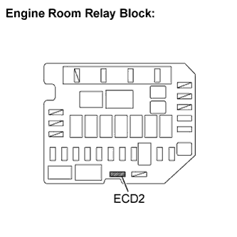
Check the ECD2 fuse resistance.
- Standard resistance:
- Below 1 Ω
Reinstall the ECD2 fuse.
|
|
||||
| OK | ||
|
||
| ||