Home › BRAKE › BRAKE CONTROL › ANTI-LOCK BRAKE SYSTEM (for Hatchback)

DTC    C1401    Front Speed Sensor RH Malfunction

DTC    C1402    Front Speed Sensor LH Malfunction

for Preparation Click here


DESCRIPTION

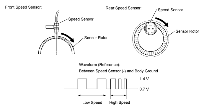
The speed sensors detect the wheel speeds and send appropriate signals to the skid control ECU. Speed sensor rotors have rows of alternating N and S magnetic poles, and their magnetic fields change as the rotors turn.
The speed sensors detect those magnetic changes and send pulse signals to the skid control ECU. The ECU monitors the wheel speeds through these pulse signals to control the ABS control system.

C115116E12


DTC Code
DTC Detection Condition
Trouble Area
C1401
C1402
When any of the following is detected:
  1. At a vehicle speed of 10 km/h (6 mph) or more, the output speed signal from one of the speed sensors is equal to or less than 14 % of that of one of other 3 sensors for 15 seconds or more.
  2. At a vehicle speed of 10 km/h (6 mph) or more, the output from one of the speed sensors is 0 km/h (0 mph) for 1 second or more.
  3. At a vehicle speed of 10 km/h (6 mph) or more, the outputs from 2 of the speed sensors are 0 km/h (0 mph) for 15 seconds or more.
  1. Front speed sensor RH/LH
  2. Speed sensor rotor
  3. Sensor installation
  4. Brake actuator assembly (Skid control ECU)
C1271
C1272
Detected only during Test Mode.
  1. Front speed sensor RH/LH
  2. Sensor installation
  3. Speed sensor rotor

HINT:
  1. DTCs C1271 and C1272 are output only in the Test Mode.
  2. DTCs C1271 and C1272 can be deleted when the speed sensor sends a vehicle speed signal or the Test Mode ends.
  3. DTCs C1401 and C1271 are for the front speed sensor RH.
  4. DTCs C1402 and C1272 are for the front speed sensor LH.


INSPECTION PROCEDURE

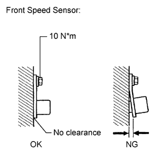
1.CHECK FRONT SPEED SENSOR INSTALLATION


    C144929E15
  1. Turn the ignition switch off.

  1. Check the speed sensor installation.

    OK:
    There is no clearance between the sensor and the front steering knuckle.
    The installation nut is tightened properly.
    Torque:
    10 N*m (105 kgf*cm, 8 ft.*lbf)


NG
INSTALL FRONT SPEED SENSOR CORRECTLY (Click here)
OK


2.CHECK FRONT SPEED SENSOR TIP
  1. Remove the front speed sensor (Click here).

  1. Check the speed sensor tip.

    OK:
    No scratches or foreign matter on the sensor tip.

    NOTICE:
    Check the speed sensor signal after cleaning or replacement (Click here).


NG
CLEAN OR REPLACE FRONT SPEED SENSOR
OK


3.INSPECT FRONT SPEED SENSOR ROTOR
  1. Check the front speed sensor rotor.

    HINT:
    The front speed sensor rotor is incorporated into the front axle hub bearing.

    OK:
    No scratches, oil, or foreign matter on the rotors.

    NOTICE:
    Check the speed sensor signal after cleaning or replacement (Click here).


NG
CLEAN OR REPLACE FRONT SPEED SENSOR ROTOR (Click here)
OK


4.REPLACE FRONT SPEED SENSOR
  1. Turn the ignition switch off.

  1. Replace the front speed sensor (Click here).

    NOTICE:
    Check the speed sensor signal after cleaning or replacement (Click here).


NEXT


5.RECONFIRM DTC
  1. Clear the DTC (Click here).

  1. Start the engine.

  1. Drive the vehicle at a speed of 40 km/h (25 mph) or more for at least 60 seconds.

  1. Check if the same DTC is recorded (Click here).
    Result 
    Result
    Proceed to
    DTC output
    A
    DTC not output
    B


B
END
A


6.REPLACE FRONT AXLE HUB BEARING
  1. Turn the ignition switch off.

  1. Replace the front axle hub bearing (Click here).

    HINT:
    The front speed sensor rotor is incorporated into the front axle hub bearing.

    CAUTION:
    Check the speed sensor signal after replacement (Click here).


NEXT


7.RECONFIRM DTC
  1. Clear the DTC (Click here).

  1. Start the engine.

  1. Drive the vehicle at a speed of 40 km/h (25 mph) or more for at least 60 seconds.

  1. Check if the same DTC is recorded (Click here).
    Result 
    Result
    Proceed to
    DTC not output
    A
    DTC output
    B

    HINT:
    If troubleshooting has been carried out according to the Problem Symptoms Table, refer back to the table and proceed to the next step (Click here).


B
REPLACE BRAKE ACTUATOR ASSEMBLY (Click here)
A

END