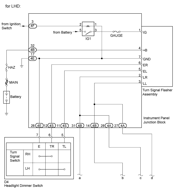
LIGHTING SYSTEM > Turn Signal Light Circuit |
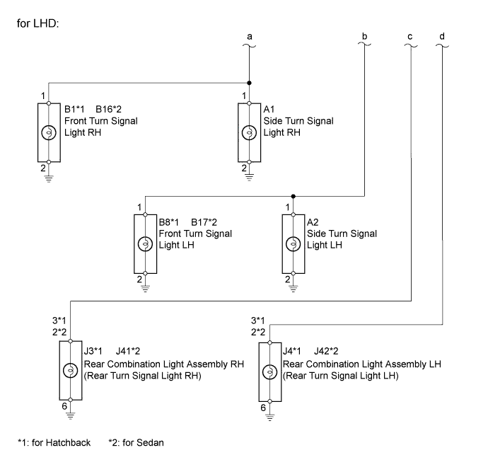
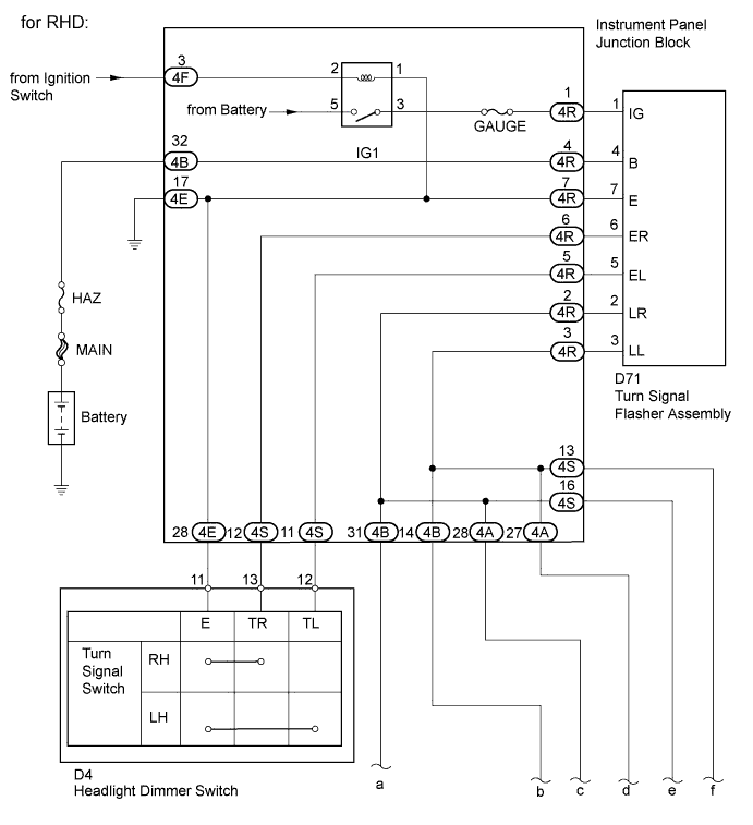
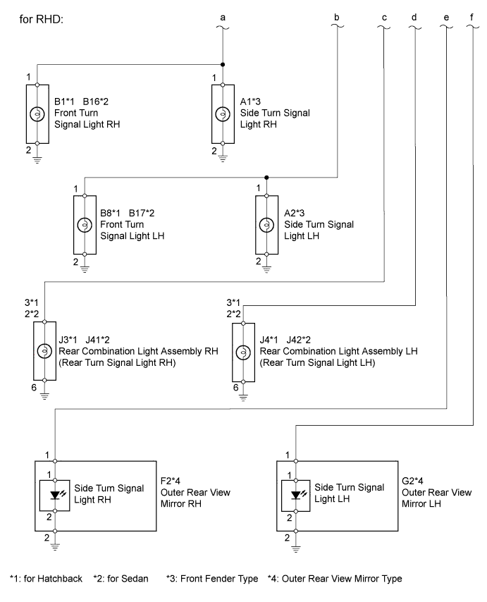
| 1.INSPECT VEHICLE TYPE |
Check the vehicle type.
| Vehicle Type | Proceed to |
| LHD models | A |
| RHD models | B |
|
| ||||
| A | |
 |
| 2.CHECK OPERATION |
When the turn signal light switch is operated, check that the appropriate turn signal light flashes.
| Result | Proceed to |
| No lights flash | A |
| Front turn signal light (LH or RH) does not flash | B |
| Side turn signal light (LH or RH) does not flash | C |
| Rear turn signal light (LH or RH) does not flash | D |
|
| ||||
|
| ||||
|
| ||||
| A | |
|
| 3.INSPECT HEADLIGHT DIMMER SWITCH |
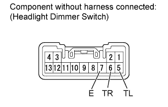 |
Remove the headlight dimmer switch.
Inspect the turn signal light switch.
Measure the resistance according to the value(s) in the table below.
| Tester Connection | Switch Condition | Specified Condition |
| 5 (TL) - 7 (E) | Turn signal light switch ON (Left) | Below 1 Ω |
| Neutral | 10 kΩ or higher | |
| 6 (TR) - 7 (E) | Turn signal light switch ON (Right) | Below 1 Ω |
| Neutral | 10 kΩ or higher |
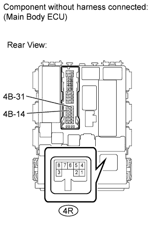
Reinstall the headlight dimmer switch.
|
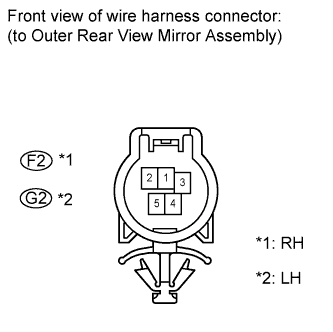
| ||||
| OK | |
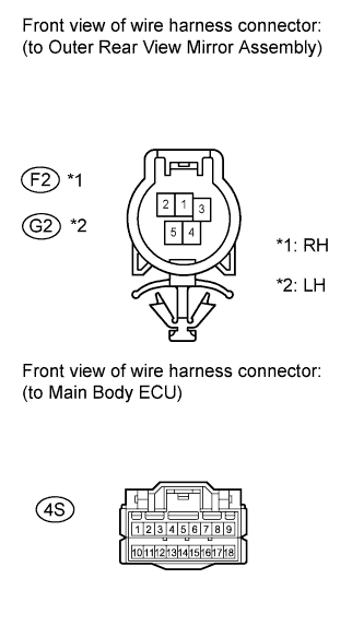
|
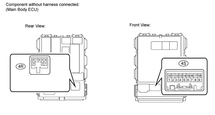
| 4.CHECK HARNESS AND CONNECTOR (HEADLIGHT DIMMER SWITCH - MAIN BODY ECU) |
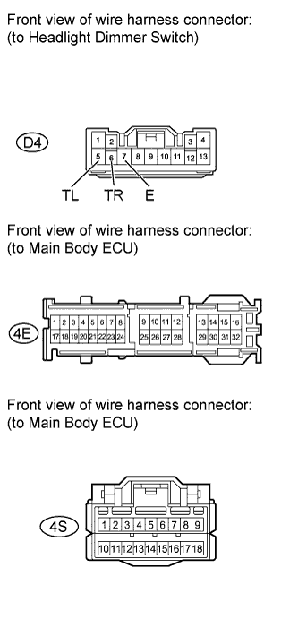 |
Disconnect the D4 headlight dimmer switch connector.
Disconnect the 4E and 4S main body ECU connectors.
Measure the resistance according to the value(s) in the table below.
| Tester Connection | Condition | Specified Condition |
| D4-5 (TL) - 4S-11 | Always | Below 1 Ω |
| D4-5 (TL) or 4S-11 - Body ground | Always | 10 kΩ or higher |
| D4-6 (TR) - 4S-12 | Always | Below 1 Ω |
| D4-6 (TR) or 4S-12 - Body ground | Always | 10 kΩ or higher |
| D4-7 (E) - 4E-28 | Always | Below 1 Ω |
Reconnect the headlight dimmer switch connector.
Reconnect the main body ECU connectors.
|
| ||||
| OK | |
|
| 5.CHECK HARNESS AND CONNECTOR (MAIN BODY ECU - BODY GROUND) |
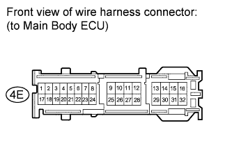 |
Disconnect the 4E main body ECU connector.
Measure the resistance according to the value(s) in the table below.
| Tester Connection | Condition | Specified Condition |
| 4E-17 - Body ground | Always | Below 1 Ω |
Reconnect the main body ECU connector.
|
| ||||
| OK | |
|
| 6.CHECK HARNESS AND CONNECTOR (HAZ FUSE - MAIN BODY ECU) |
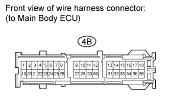 |
Disconnect the 4B main body ECU connector.
Measure the voltage according to the value(s) in the table below.
| Tester Connection | Condition | Specified Condition |
| 4B-32 - Body ground | Always | 11 to 14 V |
Reconnect the main body ECU connector.
|
| ||||
| OK | |
|
| 7.INSPECT MAIN BODY ECU |
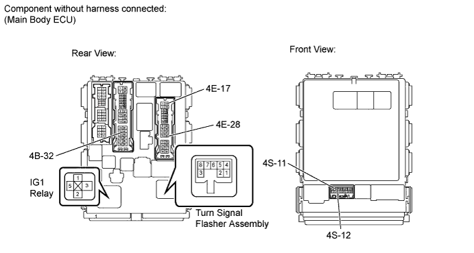
Remove the main body ECU.
Remove the IG1 relay from the main body ECU.
Measure the resistance according to the value(s) in the table below.
| Tester Connection | Condition | Specified Condition |
| 4B-32 - Turn signal flasher assembly-4 (+B) | Always | Below 1 Ω |
| 4E-17 - Turn signal flasher assembly-7 (GND) | Always | Below 1 Ω |
| 4E-28 - Turn signal flasher assembly-7(GND) | Always | Below 1 Ω |
| 4S-11 - Turn signal flasher assembly-5 (EL) | Always | Below 1 Ω |
| 4S-12 - Turn signal flasher assembly-6 (ER) | Always | Below 1 Ω |
| IG1 relay terminal 3 - Turn signal flasher assembly-1 (IG) | Always | Below 1 Ω |
Reinstall the IG1 relay.
Reinstall the main body ECU.
|
| ||||
| OK | ||
 | ||
| ||
| 8.INSPECT FRONT TURN SIGNAL LIGHT BULB |
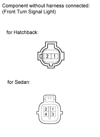 |
Remove the headlight assembly.
Apply battery voltage to the terminals and check that the front turn signal light illuminates.
| Measurement Condition | Specified Condition |
| Positive battery - Terminal 1 Negative battery - Terminal 2 | Front turn signal light illuminates |
| Result | Proceed to |
| OK | A |
| NG (Hatchback) | B |
| NG (Sedan) | C |
Reinstall the headlight assembly.
|
| ||||
|
| ||||
| A | |
|
| 9.CHECK HARNESS AND CONNECTOR (MAIN BODY ECU - FRONT TURN SIGNAL LIGHT) |
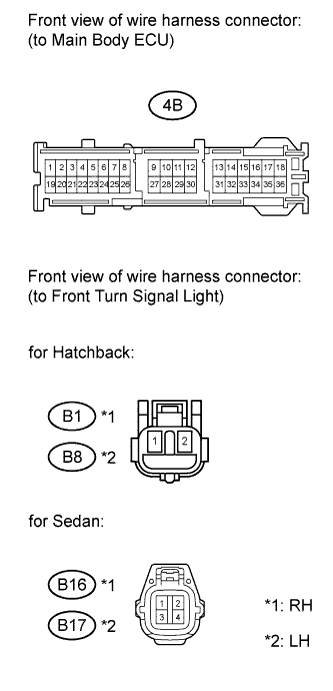 |
Disconnect the B1 and B8 front turn signal light connectors.
Disconnect the B16 and B17 front turn signal light connectors.
Disconnect the 4B main body ECU connector.
Measure the resistance according to the value(s) in the table below.
| Tester Connection | Condition | Specified Condition |
| 4B-31 - B1-1 | Always | Below 1 Ω |
| 4B-31 or B1-1 - Body ground | Always | 10 kΩ or higher |
| 4B-14 - B8-1 | Always | Below 1 Ω |
| 4B-14 or B8-1 - Body ground | Always | 10 kΩ or higher |
| Tester Connection | Condition | Specified Condition |
| 4B-31 - B16-1 | Always | Below 1 Ω |
| 4B-31 or B16-1 - Body ground | Always | 10 kΩ or higher |
| 4B-14 - B17-1 | Always | Below 1 Ω |
| 4B-14 or B17-1 - Body ground | Always | 10 kΩ or higher |
Reconnect the front turn signal light connectors.
|
| ||||
| OK | |
|
| 10.CHECK HARNESS AND CONNECTOR (FRONT TURN SIGNAL LIGHT - BODY GROUND) |
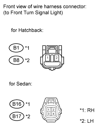 |
Disconnect the B1 and B8 front turn signal light connectors.
Disconnect the B16 and B17 front turn signal light connectors.
Measure the resistance according to the value(s) in the table below.
| Tester Connection | Condition | Specified Condition |
| B1-2 - Body ground | Always | Below 1 Ω |
| B8-2 - Body ground | Always | Below 1 Ω |
| Tester Connection | Condition | Specified Condition |
| B16-2 - Body ground | Always | Below 1 Ω |
| B17-2 - Body ground | Always | Below 1 Ω |
Reconnect the front turn signal light connectors.
|
| ||||
| OK | |
|
| 11.INSPECT MAIN BODY ECU |
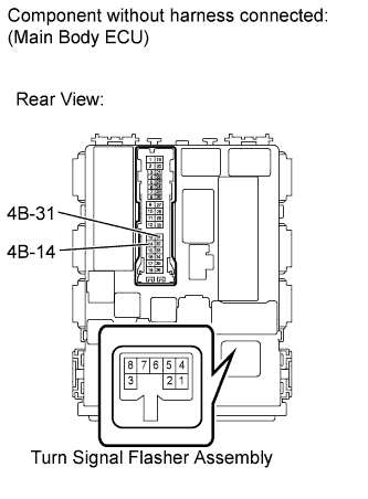 |
Remove the main body ECU.
Measure the resistance according to the value(s) in the table below.
| Tester Connection | Condition | Specified Condition |
| 4B-14 - Turn signal flasher assembly-3 (LL) | Always | Below 1 Ω |
| 4B-31 - Turn signal flasher assembly-2 (LR) | Always | Below 1 Ω |
Reinstall the main body ECU.
|
| ||||
| OK | ||
| ||
| ||
| 12.INSPECT SIDE TURN SIGNAL LIGHT ASSEMBLY |
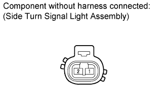 |
Remove the side turn signal light assembly.
Apply battery voltage to the terminals and check that the side turn signal light illuminates.
| Measurement Condition | Specified Condition |
| Positive battery - Terminal 1 Negative battery - Terminal 2 | Side turn signal light illuminates |
| Result | Proceed to |
| OK | A |
| NG (Hatchback) | B |
| NG (Sedan) | C |
Reinstall the side turn signal light assembly.
|
| ||||
|
| ||||
| A | |
|
| 13.CHECK HARNESS AND CONNECTOR (MAIN BODY ECU - SIDE TURN SIGNAL LIGHT ASSEMBLY) |
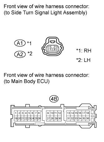 |
Disconnect the A1 and A2 side turn signal light assembly connectors.
Disconnect the 4B main body ECU connector.
Measure the resistance according to the value(s) in the table below.
| Tester Connection | Condition | Specified Condition |
| 4B-31 - A1-1 | Always | Below 1 Ω |
| 4B-31 or A1-1 - Body ground | Always | 10 kΩ or higher |
| 4B-14 - A2-1 | Always | Below 1 Ω |
| 4B-14 or A2-1 - Body ground | Always | 10 kΩ or higher |
Reconnect the side turn signal light assembly connectors.
Reconnect the main body ECU connector.
|
| ||||
| OK | |
|
| 14.CHECK HARNESS AND CONNECTOR (SIDE TURN SIGNAL LIGHT ASSEMBLY - BODY GROUND) |
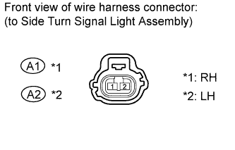 |
Disconnect the A1 and A2 side turn signal light assembly connectors.
Measure the resistance according to the value(s) in the table below.
| Tester Connection | Condition | Specified Condition |
| A1-2 - Body ground | Always | Below 1 Ω |
| A2-2 - Body ground | Always | Below 1 Ω |
Reconnect the side turn signal light assembly connectors.
|
| ||||
| OK | |
|
| 15.INSPECT MAIN BODY ECU |
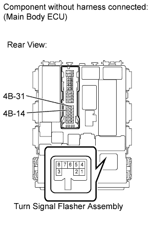 |
Remove the main body ECU.
Measure the resistance according to the value(s) in the table below.
| Tester Connection | Condition | Specified Condition |
| 4B-14 - Turn signal flasher assembly-3 (LL) | Always | Below 1 Ω |
| 4B-31 - Turn signal flasher assembly-2 (LR) | Always | Below 1 Ω |
Reinstall the main body ECU.
|
| ||||
| OK | ||
| ||
| ||
| 16.INSPECT REAR TURN SIGNAL LIGHT BULB |
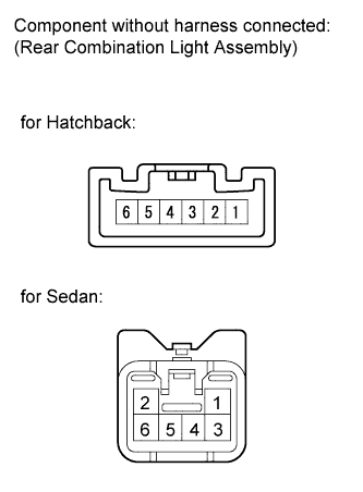 |
Remove the rear combination light assembly.
Apply battery voltage to the terminals and check that the rear turn signal light illuminates.
| Measurement Condition | Specified Condition |
| Positive battery - Terminal 3 Negative battery - Terminal 6 | Rear turn signal light illuminates |
| Measurement Condition | Specified Condition |
| Positive battery - Terminal 2 Negative battery - Terminal 6 | Rear turn signal light illuminates |
| Result | Proceed to |
| OK | A |
| NG (Hatchback) | B |
| NG (Sedan) | C |
Reinstall the rear combination light assembly.
|
| ||||
|
| ||||
| A | |
|
| 17.CHECK HARNESS AND CONNECTOR (MAIN BODY ECU - REAR TURN SIGNAL LIGHT) |
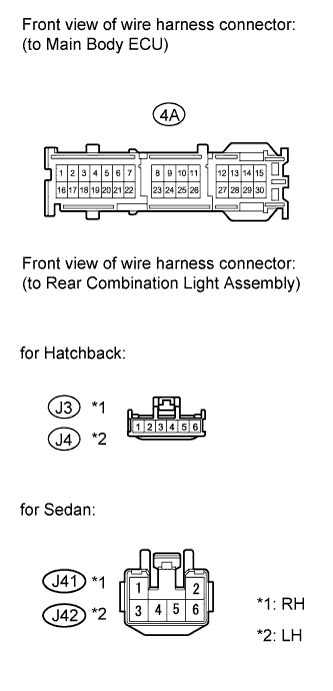 |
Disconnect the J3 and J4 Rear combination light assembly connectors.
Disconnect the J41 and J42 Rear combination light assembly connectors.
Disconnect the 4A main body ECU connector.
Measure the resistance according to the value(s) in the table below.
| Tester Connection | Condition | Specified Condition |
| 4A-28 - J3-3 | Always | Below 1 Ω |
| 4A-28 or J3-3 - Body ground | Always | 10 kΩ or higher |
| 4A-27 - J4-3 | Always | Below 1 Ω |
| 4A-27 or J4-3 - Body ground | Always | 10 kΩ or higher |
| Tester Connection | Condition | Specified Condition |
| 4A-28 - J41-2 | Always | Below 1 Ω |
| 4A-28 or J41-2 - Body ground | Always | 10 kΩ or higher |
| 4A-27 - J42-2 | Always | Below 1 Ω |
| 4A-27 or J42-2 - Body ground | Always | 10 kΩ or higher |
Reconnect the rear combination light assembly connectors.
Reconnect the main body ECU connector.
|
| ||||
| OK | |
|
| 18.CHECK HARNESS AND CONNECTOR (REAR TURN SIGNAL LIGHT - BODY GROUND) |
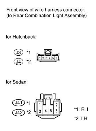 |
Disconnect the J3 and J4 rear combination light assembly connectors.
Disconnect the J41 and J42 rear combination light assembly connectors.
Measure the resistance according to the value(s) in the table below.
| Tester Connection | Condition | Specified Condition |
| J3-6 - Body ground | Always | Below 1 Ω |
| J4-6 - Body ground | Always | Below 1 Ω |
| Tester Connection | Condition | Specified Condition |
| J41-6 - Body ground | Always | Below 1 Ω |
| J42-6 - Body ground | Always | Below 1 Ω |
Reconnect the rear combination light assembly connectors.
|
| ||||
| OK | |
|
| 19.INSPECT MAIN BODY ECU |
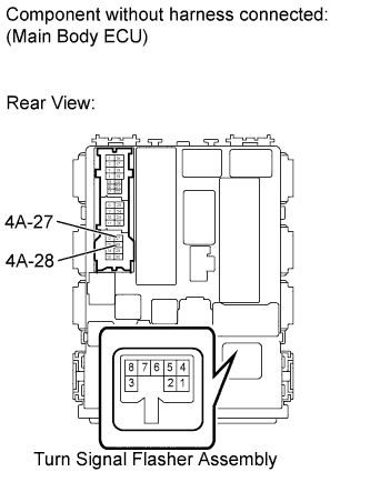 |
Remove the main body ECU.
Measure the resistance according to the value(s) in the table below.
| Tester Connection | Condition | Specified Condition |
| 4A-27 - Turn signal flasher assembly-3 (LL) | Always | Below 1 Ω |
| 4A-28 - Turn signal flasher assembly-2 (LR) | Always | Below 1 Ω |
Reinstall the main body ECU.
|
| ||||
| OK | ||
| ||
| ||
| 20.CHECK OPERATION |
When the turn signal light switch is operated, check that the appropriate turn signal light flashes.
| Result | Proceed to |
| No lights flash | A |
| Front turn signal light (LH or RH) does not flash | B |
| Side turn signal light (LH or RH) does not flash | C |
| Rear turn signal light (LH or RH) does not flash | D |
|
| ||||
|
| ||||
|
| ||||
| A | |
|
| 21.INSPECT HEADLIGHT DIMMER SWITCH |
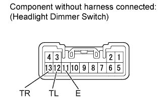 |
Remove the headlight dimmer switch.
Inspect the turn signal light switch.
Measure the resistance according to the value(s) in the table below.
| Tester Connection | Switch Condition | Specified Condition |
| 12 (TL) - 11 (E) | Turn signal light switch ON (Left) | Below 1 Ω |
| Neutral | 10 kΩ or higher | |
| 13 (TR) - 11 (E) | Turn signal light switch ON (Right) | Below 1 Ω |
| Neutral | 10 kΩ or higher |
Reinstall the headlight dimmer switch.
|
| ||||
| OK | |
|
| 22.CHECK HARNESS AND CONNECTOR (HEADLIGHT DIMMER SWITCH - MAIN BODY ECU) |
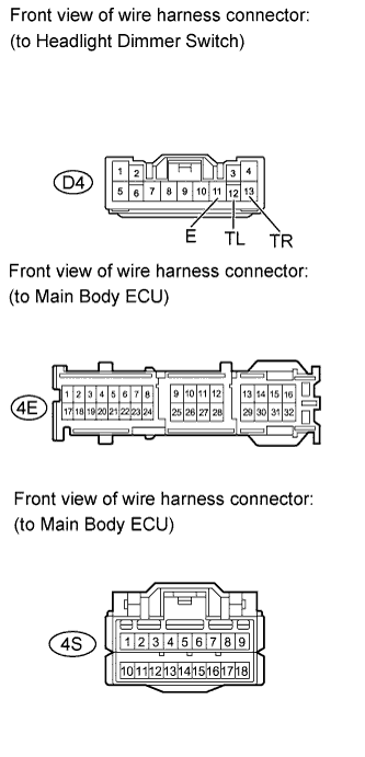 |
Disconnect the D4 headlight dimmer switch connector.
Disconnect the 4E and 4S main body ECU connectors.
Measure the resistance according to the value(s) in the table below.
| Tester Connection | Condition | Specified Condition |
| D4-12 (TL) - 4S-11 | Always | Below 1 Ω |
| D4-12 (TL) or 4S-11 - Body ground | Always | 10 kΩ or higher |
| D4-13 (TR) - 4S-12 | Always | Below 1 Ω |
| D4-13 (TR) or 4S-12 - Body ground | Always | 10 kΩ or higher |
| D4-11 (E) - 4E-28 | Always | Below 1 Ω |
Reconnect the headlight dimmer switch connector.
Reconnect the main body ECU connectors.
|
| ||||
| OK | |
|
| 23.CHECK HARNESS AND CONNECTOR (MAIN BODY ECU - BODY GROUND) |
|
Disconnect the 4E main body ECU connector.
Measure the resistance according to the value(s) in the table below.
| Tester Connection | Condition | Specified Condition |
| 4E-17 - Body ground | Always | Below 1 Ω |
Reconnect the main body ECU connector.
|
| ||||
| OK | |
|
| 24.CHECK HARNESS AND CONNECTOR (HAZ FUSE - MAIN BODY ECU) |
|
Disconnect the 4B main body ECU connector.
Measure the voltage according to the value(s) in the table below.
| Tester Connection | Condition | Specified Condition |
| 4B-32 - Body ground | Always | 11 to 14 V |
Reconnect the main body ECU connector.
|
| ||||
| OK | |
|
| 25.INSPECT MAIN BODY ECU |
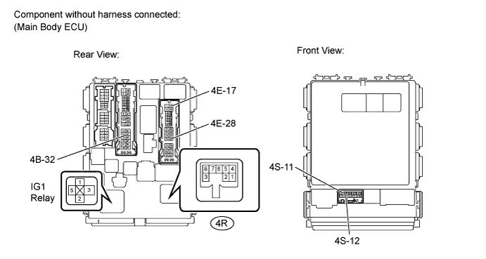
Remove the main body ECU.
Remove the IG1 relay from the main body ECU.
Measure the resistance according to the value(s) in the table below.
| Tester Connection | Condition | Specified Condition |
| 4B-32 - 4R-4 | Always | Below 1 Ω |
| 4E-17 - 4R-7 | Always | Below 1 Ω |
| 4E-28 - 4R-7 | Always | Below 1 Ω |
| 4S-11 - 4R-5 | Always | Below 1 Ω |
| 4S-12 - 4R-6 | Always | Below 1 Ω |
| IG1 relay terminal 3 - 4R-1 | Always | Below 1 Ω |
Reinstall the IG1 relay.
Reinstall the main body ECU.
|
| ||||
| OK | |
|
| 26.CHECK HARNESS AND CONNECTOR (MAIN BODY ECU - TURN SIGNAL FLASHER ASSEMBLY) |
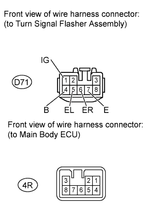 |
Disconnect the 4R main body ECU connector.
Disconnect the D71 turn signal flasher assembly connector.
Measure the resistance according to the value (s) in the table below.
| Tester Connection | Condition | Specified Condition |
| 4R-1 - D71-1 (IG) | Always | Below 1 Ω |
| 4R-4 - D71-4 (B) | Always | Below 1 Ω |
| 4R-5 - D71-5 (EL) | Always | Below 1 Ω |
| 4R-6 - D71-6 (ER) | Always | Below 1 Ω |
| 4R-7 - D71-7 (E) | Always | Below 1 Ω |
Reconnect the turn signal flasher assembly connector.
Reconnect the main body ECU connector.
|
| ||||
| OK | ||
| ||
| ||
| 27.INSPECT FRONT TURN SIGNAL LIGHT BULB |
|
Remove the headlight assembly.
Apply battery voltage to the terminals and check that the front turn signal light illuminates.
| Measurement Condition | Specified Condition |
| Positive battery - Terminal 1 Negative battery - Terminal 2 | Front turn signal light illuminates |
| Result | Proceed to |
| OK | A |
| NG (Hatchback) | B |
| NG (Sedan) | C |
Reinstall the headlight assembly.
|
| ||||
|
| ||||
| A | |
|
| 28.CHECK HARNESS AND CONNECTOR (MAIN BODY ECU - FRONT TURN SIGNAL LIGHT) |
|
Disconnect the B1 and B8 front turn signal light connectors.
Disconnect the B16 and B17 front turn signal light connectors.
Disconnect the 4B main body ECU connector.
Measure the resistance according to the value(s) in the table below.
| Tester Connection | Condition | Specified Condition |
| 4B-31 - B1-1 | Always | Below 1 Ω |
| 4B-31 or B1-1 - Body ground | Always | 10 kΩ or higher |
| 4B-14 - B8-1 | Always | Below 1 Ω |
| 4B-14 or B8-1 - Body ground | Always | 10 kΩ or higher |
| Tester Connection | Condition | Specified Condition |
| 4B-31 - B16-1 | Always | Below 1 Ω |
| 4B-31 or B16-1 - Body ground | Always | 10 kΩ or higher |
| 4B-14 - B17-1 | Always | Below 1 Ω |
| 4B-14 or B17-1 - Body ground | Always | 10 kΩ or higher |
Reconnect the front turn signal light connectors.
|
| ||||
| OK | |
|
| 29.CHECK HARNESS AND CONNECTOR (FRONT TURN SIGNAL LIGHT - BODY GROUND) |
|
Disconnect the B1 and B8 front turn signal light connectors.
Disconnect the B16 and B17 front turn signal light connectors.
Measure the resistance according to the value(s) in the table below.
| Tester Connection | Condition | Specified Condition |
| B1-2 - Body ground | Always | Below 1 Ω |
| B8-2 - Body ground | Always | Below 1 Ω |
| Tester Connection | Condition | Specified Condition |
| B16-2 - Body ground | Always | Below 1 Ω |
| B17-2 - Body ground | Always | Below 1 Ω |
Reconnect the front turn signal light connectors.
|
| ||||
| OK | |
|
| 30.INSPECT MAIN BODY ECU |
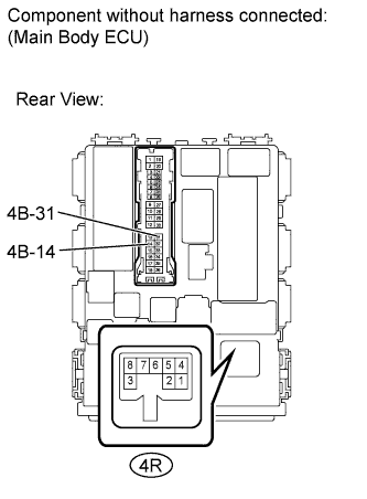 |
Remove the main body ECU.
Measure the resistance according to the value(s) in the table below.
| Tester Connection | Condition | Specified Condition |
| 4B-14 - 4R-3 | Always | Below 1 Ω |
| 4B-31 - 4R-2 | Always | Below 1 Ω |
Reinstall the main body ECU.
|
| ||||
| OK | |
|
| 31.CHECK HARNESS AND CONNECTOR (MAIN BODY ECU - TURN SIGNAL FLASHER ASSEMBLY) |
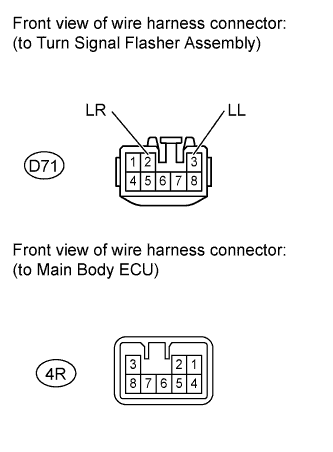 |
Disconnect the 4R main body ECU connector.
Disconnect the D71 turn signal flasher assembly connector.
Measure the resistance according to the value (s) in the table below.
| Tester Connection | Condition | Specified Condition |
| 4R-2 - D71-2 (LR) | Always | Below 1 Ω |
| 4R-3 - D71-3 (LL) | Always | Below 1 Ω |
Reconnect the turn signal flasher assembly connector.
Reconnect the main body ECU connector.
|
| ||||
| OK | ||
| ||
| ||
| 32.INSPECT SIDE TURN SIGNAL LIGHT ASSEMBLY |
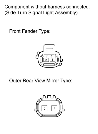 |
Remove the side turn signal light assembly.
Apply battery voltage to the terminals and check that the side turn signal light illuminates.
| Measurement Condition | Specified Condition |
| Positive battery - Terminal 1 Negative battery - Terminal 2 | Side turn signal light illuminates |
| Result | Proceed to |
| OK (Front Fender Type) | A |
| OK (Outer Rear View Mirror Type) | B |
| NG (Hatchback) | C |
| NG (Sedan with Front Fender Type) | D |
| NG (Sedan with Outer Rear View Mirror Type) | E |
Reinstall the side turn signal light assembly.
|
| ||||
|
| ||||
|
| ||||
|
| ||||
| A | |
|
| 33.CHECK HARNESS AND CONNECTOR (MAIN BODY ECU - SIDE TURN SIGNAL LIGHT ASSEMBLY) |
|
Disconnect the A1 and A2 side turn signal light assembly connectors.
Disconnect the 4B main body ECU connector.
Measure the resistance according to the value(s) in the table below.
| Tester Connection | Condition | Specified Condition |
| 4B-31 - A1-1 | Always | Below 1 Ω |
| 4B-31 or A1-1 - Body ground | Always | 10 kΩ or higher |
| 4B-14 - A2-1 | Always | Below 1 Ω |
| 4B-14 or A2-1 - Body ground | Always | 10 kΩ or higher |
Reconnect the side turn signal light assembly connectors.
Reconnect the main body ECU connector.
|
| ||||
| OK | |
|
| 34.CHECK HARNESS AND CONNECTOR (SIDE TURN SIGNAL LIGHT ASSEMBLY - BODY GROUND) |
|
Disconnect the A1 and A2 side turn signal light assembly connectors.
Measure the resistance according to the value(s) in the table below.
| Tester Connection | Condition | Specified Condition |
| A1-2 - Body ground | Always | Below 1 Ω |
| A2-2 - Body ground | Always | Below 1 Ω |
Reconnect the side turn signal light assembly connectors.
|
| ||||
| OK | |
|
| 35.INSPECT MAIN BODY ECU |
 |
Remove the main body ECU.
Measure the resistance according to the value(s) in the table below.
| Tester Connection | Condition | Specified Condition |
| 4B-14 - 4R-3 | Always | Below 1 Ω |
| 4B-31 - 4R-2 | Always | Below 1 Ω |
Reinstall the main body ECU.
|
| ||||
| OK | |
|
| 36.CHECK HARNESS AND CONNECTOR (MAIN BODY ECU - TURN SIGNAL FLASHER ASSEMBLY) |
|
Disconnect the 4R main body ECU connector.
Disconnect the D71 turn signal flasher assembly connector.
Measure the resistance according to the value (s) in the table below.
| Tester Connection | Condition | Specified Condition |
| 4R-2 - D71-2 (LR) | Always | Below 1 Ω |
| 4R-3 - D71-3 (LL) | Always | Below 1 Ω |
Reconnect the turn signal flasher assembly connector.
Reconnect the main body ECU connector.
|
| ||||
| OK | ||
| ||
| ||
| 37.INSPECT OUTER REAR VIEW MIRROR ASSEMBLY (SYSTEM VOLTAGE) |
 |
Disconnect the F2 and G2 outer rear view mirror assembly connectors.
Measure the voltage according to the value(s) in the table below.
| Tester Connection | Switch Condition | Specified Condition |
| F2-1 - Body ground | Turn signal (right turn) OFF → ON | Below 1 V → 11 to 14 V (60 to 120 times per minute |
| G2-1 - Body ground | Turn signal (left turn) OFF → ON | Below 1 V → 11 to 14 V (60 to 120 times per minute |
Reconnect the outer rear view mirror assembly connectors.
|
| ||||
| OK | |
|
| 38.CHECK HARNESS AND CONNECTOR (OUTER REAR VIEW MIRROR ASSEMBLY - BODY GROUND) |
|
Disconnect the F2 and G2 outer rear view mirror assembly connectors.
Measure the resistance according to the value(s) in the table below.
| Tester Connection | Switch Condition | Specified Condition |
| F2-2 - Body ground | Always | Below 1 Ω |
| G2-2 - Body ground | Always | Below 1 Ω |
Reconnect the outer rear view mirror assembly connectors.
|
| ||||
| OK | ||
| ||
| ||
| 39.CHECK HARNESS AND CONNECTOR (OUTER REAR VIEW MIRROR ASSEMBLY - MAIN BODY ECU) |
 |
Disconnect the F2 and G2 outer rear view mirror assembly connectors.
Disconnect the 4S main body ECU connector.
Measure the resistance according to the value(s) in the table below.
| Tester Connection | Switch Condition | Specified Condition |
| F2-1 - 4S-16 | Always | Below 1 Ω |
| F2-1 or 4S-16 - Body ground | Always | 10 kΩ or higher |
| G2-1 - 4S-13 | Always | Below 1 Ω |
| G2-1 or 4S-13 - Body ground | Always | 10 kΩ or higher |
Reconnect the outer rear view mirror assembly connectors.
Reconnect the main body ECU connector.
|
| ||||
| OK | |
|
| 40.INSPECT MAIN BODY ECU |
Remove the main body ECU.
Measure the resistance according to the value(s) in the table below.
| Tester Connection | Condition | Specified Condition |
| 4S-13 - 4R-3 | Always | Below 1 Ω |
| 4S-16 - 4R-2 | Always | Below 1 Ω |
Reinstall the main body ECU.
|
| ||||
| OK | |
|
| 41.CHECK HARNESS AND CONNECTOR (MAIN BODY ECU - TURN SIGNAL FLASHER ASSEMBLY) |
|
Disconnect the 4R main body ECU connector.
Disconnect the D71 turn signal flasher assembly connector.
Measure the resistance according to the value (s) in the table below.
| Tester Connection | Condition | Specified Condition |
| 4R-2 - D71-2 (LR) | Always | Below 1 Ω |
| 4R-3 - D71-3 (LL) | Always | Below 1 Ω |
Reconnect the turn signal flasher assembly connector.
Reconnect the main body ECU connector.
|
| ||||
| OK | ||
| ||
| ||
| 42.INSPECT REAR TURN SIGNAL LIGHT BULB |
|
Remove the rear combination light assembly.
Apply battery voltage to the terminals and check that the rear turn signal light illuminates.
| Measurement Condition | Specified Condition |
| Positive battery - Terminal 3 Negative battery - Terminal 6 | Rear turn signal light illuminates |
| Measurement Condition | Specified Condition |
| Positive battery - Terminal 2 Negative battery - Terminal 6 | Rear turn signal light illuminates |
| Result | Proceed to |
| OK | A |
| NG (Hatchback) | B |
| NG (Sedan) | C |
Reinstall the rear combination light assembly.
|
| ||||
|
| ||||
| A | |
|
| 43.CHECK HARNESS AND CONNECTOR (MAIN BODY ECU - REAR TURN SIGNAL LIGHT) |
|
Disconnect the J3 and J4 Rear combination light assembly connectors.
Disconnect the J41 and J42 Rear combination light assembly connectors.
Disconnect the 4A main body ECU connector.
Measure the resistance according to the value(s) in the table below.
| Tester Connection | Condition | Specified Condition |
| 4A-28 - J3-3 | Always | Below 1 Ω |
| 4A-28 or J3-3 - Body ground | Always | 10 kΩ or higher |
| 4A-27 - J4-3 | Always | Below 1 Ω |
| 4A-27 or J4-3 - Body ground | Always | 10 kΩ or higher |
| Tester Connection | Condition | Specified Condition |
| 4A-28 - J41-2 | Always | Below 1 Ω |
| 4A-28 or J41-2 - Body ground | Always | 10 kΩ or higher |
| 4A-27 - J42-2 | Always | Below 1 Ω |
| 4A-27 or J42-2 - Body ground | Always | 10 kΩ or higher |
Reconnect the rear combination light assembly connectors.
Reconnect the main body ECU connector.
|
| ||||
| OK | |
|
| 44.CHECK HARNESS AND CONNECTOR (REAR TURN SIGNAL LIGHT - BODY GROUND) |
|
Disconnect the J3 and J4 Rear combination light assembly connectors.
Disconnect the J41 and J42 rear combination light assembly connectors.
Measure the resistance according to the value(s) in the table below.
| Tester Connection | Condition | Specified Condition |
| J3-6 - Body ground | Always | Below 1 Ω |
| J4-6 - Body ground | Always | Below 1 Ω |
| Tester Connection | Condition | Specified Condition |
| J41-6 - Body ground | Always | Below 1 Ω |
| J42-6 - Body ground | Always | Below 1 Ω |
Reconnect the rear combination light assembly connectors.
|
| ||||
| OK | |
|
| 45.INSPECT MAIN BODY ECU |
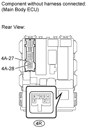 |
Remove the main body ECU.
Measure the resistance according to the value(s) in the table below.
| Tester Connection | Condition | Specified Condition |
| 4A-27 - 4R-3 | Always | Below 1 Ω |
| 4A-28 - 4R-2 | Always | Below 1 Ω |
Reinstall the main body ECU.
|
| ||||
| OK | |
|
| 46.CHECK HARNESS AND CONNECTOR (MAIN BODY ECU - TURN SIGNAL FLASHER ASSEMBLY) |
|
Disconnect the 4R main body ECU connector.
Disconnect the D71 turn signal flasher assembly connector.
Measure the resistance according to the value (s) in the table below.
| Tester Connection | Condition | Specified Condition |
| 4R-2 - D71-2 (LR) | Always | Below 1 Ω |
| 4R-3 - D71-3 (LL) | Always | Below 1 Ω |
Reconnect the turn signal flasher assembly connector.
Reconnect the main body ECU connector.
|
| ||||
| OK | ||
| ||
| ||

