CROSSMEMBER-ENGINE CRADLE
REMOVAL
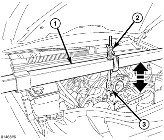
1. Support engine using engine support fixture No. 8534 or equivalent.
2. Remove the front skid plates. (Refer to 13 - FRAME & BUMPERS/FRAME/SKID PLATE-FRONT - REMOVAL)
3. Remove the rotors. (Refer to 5 - BRAKES/HYDRAULIC/MECHANICAL/REMOVAL - FRONT DISC BRAKE ROTOR)
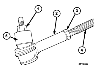
NOTE: Do not twist the boot anytime during removal or installation.
4. Remove the outer tie rod end (2) nut (1) from the ball stud.
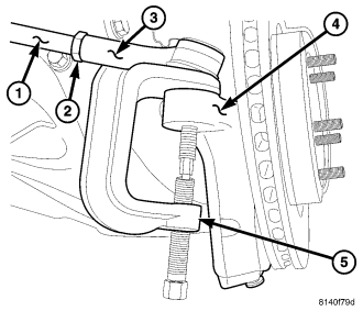
5. Separate the outer tie rod end (3) from the knuckle with puller tool No. 8677 (5).
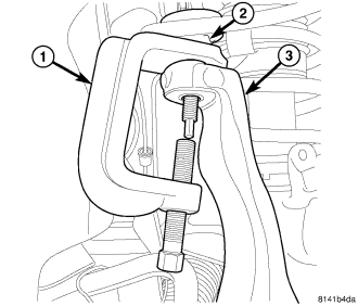
6. Remove the upper ball joint nut.
7. Separate the upper ball joint (2) from the knuckle (3) using puller tool No. 8677 (1).
8. Remove the axle nuts and reinstall a couple threads.
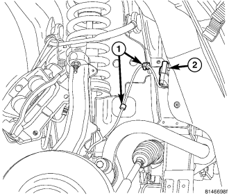
9. Disconnect the speed sensors (2) and separate the harness from the support clips (1).
10. Remove the lower ball joint nut.
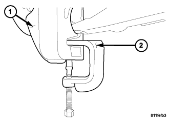
11. Separate the lower ball joint from the knuckle (1) using puller tool No. C-4150A (2).
12. Remove the axle nuts (3) and remove the knuckles (1) from the vehicle.

13. Remove the lower clevis bolts.
On 4WD models:
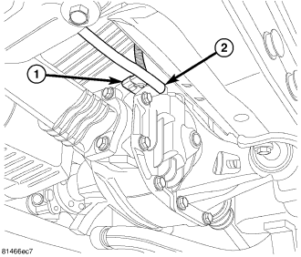
1. Disconnect the electrical connector (1), if equipped, and the vent hose (2).
2. Remove the right halfshaft.
3. Separate the propeller shaft as necessary, and position out of the way. (Refer to 3 - DIFFERENTIAL & DRIVELINE/PROPELLER SHAFT/PROPELLER SHAFT-FRONT - REMOVAL)
4. Drain the differential.
5. Support the differential with a suitable lifting device.
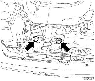
6. Remove the front differential front bolts.
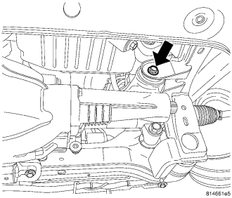
7. Remove the differential right bolt.
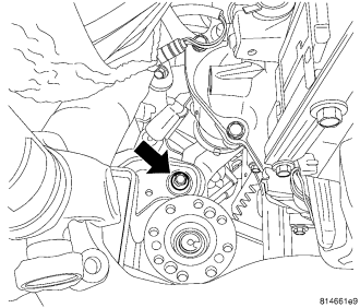
8. Remove the differential rear bolt.
9. Remove the differential assembly with the left halfshaft still attached.
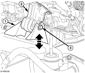
14. Loosen the engine mount bolts.
15. Raise the engine so that the weight is off of the mount bolts.
16. Secure the steering wheel in the straight ahead position.
17. Remove the steering gear as necessary. (Refer to 19 - STEERING/GEAR - REMOVAL)
18. Support the cradle with suitable lifting device.
19. Using a grease pencil or equivalent, mark the location of the engine support cradle on the underbody.
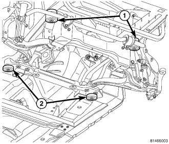
20. Remove the four bolts at each corner and lower the cradle.
21. Remove the lower control arms.
22. Remove the sway bar.
INSTALLATION
1. Install the sway bar onto the engine cradle as necessary. (Refer to 2 - SUSPENSION/FRONT/STABILIZER BAR - INSTALLATION)
2. Install the lower control arms as necessary. (Refer to 2 - SUSPENSION/FRONT/LOWER CONTROL ARM - INSTALLATION)
3. Raise the engine cradle into position guiding the engine mount bolts into the engine cradle slots.
4. Install the four engine cradle bolts (1 & 2).
5. Align the engine cradle to the marks made during removal and tighten the front bolts (1) to 203 N·m (150 ft. lbs.).
6. Tighten the rear bolts (2) to 122 N·m (90 ft. lbs.).
7. Install the steering gear as necessary. (Refer to 19 - STEERING/GEAR - INSTALLATION)
8. Lower the engine fully onto the engine mounts.
9. Tighten the engine mount bolts to 111 N·m (82 ft. lbs.).
On 4WD models:
1. Position the front differential into the vehicle and install the bolts.
2. Tighten the rear bolt to 102 N·m (75 ft. lbs.).
3. Tighten the right differential bolt to 102 N·m (75 ft. lbs.).
4. Tighten the front differential front bolts to 54 N·m (40 ft. lbs.).
5. Install the propeller shaft as necessary. (Refer to 3 - DIFFERENTIAL & DRIVELINE/PROPELLER SHAFT/PROPELLER SHAFT - INSTALLATION)
6. Install the right halfshaft onto the differential.
7. Connect the electrical connector (1) (if equipped) and the vent hose (2).
10. Install the lower clevis bolts and tighten to 169 N·m (125 ft. lbs.).
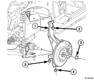
11. Install the knuckles (1) and install the halfshaft nut (3). (if equipped)
12. Tighten the halfshaft nut (3) to 251 N·m (185 ft. lbs.). (if equipped)
13. Install the lower ball joint into the knuckle.
14. Install the lower ball joint nut (4) and tighten the nut to 81 N·m (60 ft. lbs.).
15. Install the upper ball joint into the knuckle.
16. Install the upper ball joint nut (2). Tighten the nut to 81 N·m (60 ft. lbs.).
17. Install the outer tie rod end into the steering knuckle.
18. Tighten the ball stud nut (5) on the ball stud to 75 N·m (55 ft. lbs.).
19. Connect the speed sensor electrical connectors (2) and fasten the harness support clips (1) fully.
20. Install the rotors. (Refer to 5 - BRAKES/HYDRAULIC/MECHANICAL/ROTORS - INSTALLATION - FRONT DISC BRAKE ROTOR)
21. Check and fill the front differential as necessary. (Refer to LUBRICATION & MAINTENANCE/FLUID CAPACITIES - SPECIFICATIONS)
22. Install the front skid plates. (Refer to 13 - FRAME & BUMPERS/FRAME/FRONT SKID PLATE - INSTALLATION)
23. Check and adjust front wheel alignment as necessary. (Refer to 2 - SUSPENSION/WHEEL ALIGNMENT - STANDARD PROCEDURE - COMPLETE)