AUTOMATIC - CVT-SERVICE INFORMATION
DESCRIPTION
The continuously variable transmission (CVT) has a torque converter and allows optimal driving force in response to the accelerator pedal operation, therefore giving us smooth driving without shift shock. The CVT also has a manual mode function for both smooth driving without shift shock, and enjoyable driving with manual ratio selection.
The CVT allows for maximum driving force and performance when compared to a conventional A/T. When the throttle is fully opened, driving force for the conventional automatic transmission changes unevenly because the ratio is shifted in steps. On the other hand, driving force for the CVT changes smoothly because it is possible for it to accelerate while keeping it in the peak power range of the engine. Therefore, CVT avoids the loss of driving force, and enables smooth and shock free driving.
Coordinated control of the engine and the multifaceted shift diagram have made it possible to realize both, smooth and powerful driving with a good ratio change response and an improvement in fuel consumption.
OPERATION
PARK POWERFLOW
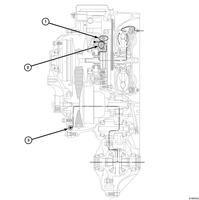
| PARK |
| 1 - REVERSE BRAKE (RELEASED) |
| 2 - FORWARD CLUTCH (RELEASED) |
| 3- PARKING GEAR (FIXED) |
When the forward clutch and the reverse brake are released, the driving force from the engine runs idly and power is not transmitted to the primary pulley.
When the parking gear is fixed, the torque load from the tires is not transmitted up to the primary pulley.
REVERSE POWERFLOW
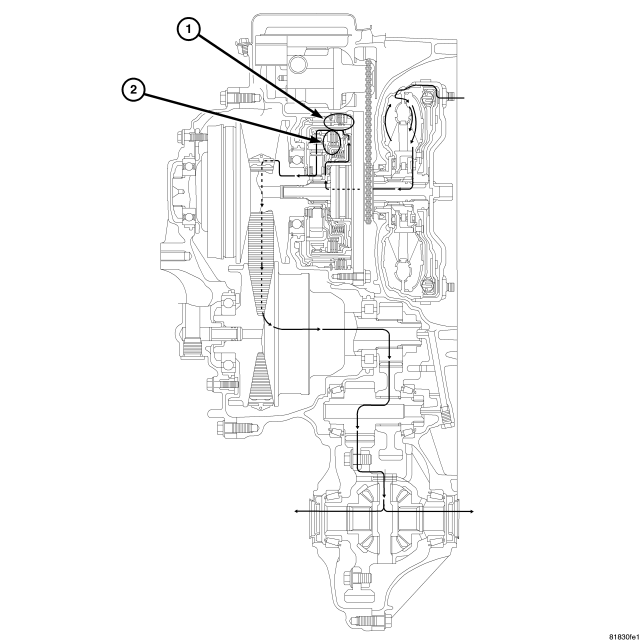
| REVERSE |
| 1 - REVERSE BRAKE (ENGAGED) |
| 2 - FORWARD CLUTCH (RELEASED) |
When the reverse brake is engaged, the planetary carrier is fixed and the driving force from the engine rotates the sun gear reversely.
Therefore, the primary pulley is rotated reversely and the driving force is outputted in the reverse rotating direction.
NEUTRAL POWERFLOW
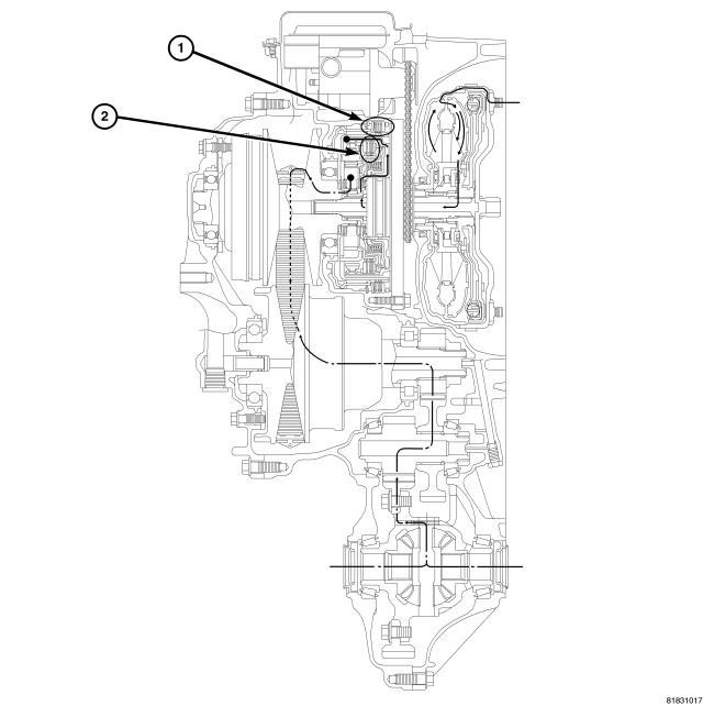
| NEUTRAL |
| 1 - REVERSE BRAKE (RELEASED) |
| 2 - FORWARD CLUTCH (RELEASED) |
When the forward clutch and the reverse brake are released, the driving force from the engine runs idly and is not transmitted to the primary pulley.
When the forward clutch and the reverse brake are released, the planetary carrier runs idly and the torque from the tires are not transmitted.
DRIVE POWERFLOW
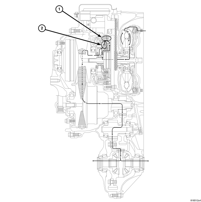
| DRIVE |
| 1 - REVERSE BRAKE (RELEASED) |
| 2 - FORWARD CLUTCH (ENGAGED) |
When the forward clutch is engaged, the driving force from the engine rotates the sun gear normally through the forward clutch.
Therefore, the primary pulley is rotated normally and the driving force is outputted in the normally rotated direction.
SHIFT LOW TO HIGH - PHASE 1
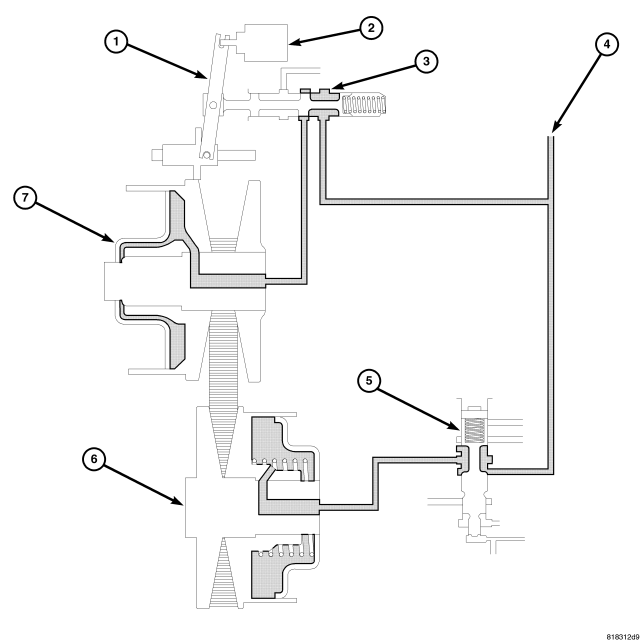
| SHIFT LOW TO HIGH |
| 1 - PULLEY RATIO LINKAGE |
5 - SECONDARY VALVE |
| 2 - STEPPER MOTOR |
6 - SECONDARY PULLEY |
| 3 - RATIO CONTROL VALVE |
7 - PRIMARY PULLEY |
| 4 - LINE PRESSURE |
When the line pressure circuit is closed by the ratio control valve, the line pressure is not applied to the primary pulley.
When the secondary valve moves downwards, line pressure is applied to the secondary pulley.
SHIFT LOW TO HIGH - PHASE 2
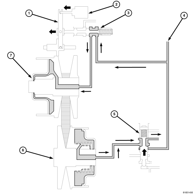
| SHIFT LOW TO HIGH 2 |
| 1 - PULLEY RATIO LINKAGE |
5 - SECONDARY VALVE |
| 2 - STEPPER MOTOR |
6 - SECONDARY PULLEY |
| 3 - RATIO CONTROL VALVE |
7 - PRIMARY PULLEY |
| 4 - LINE PRESSURE |
The pulley ratio linkage moves to the left direction of the stepper motor. The line pressure circuit opens due to the movement of the ratio control valve which links to the pulley linkage, and line pressure is applied to the primary pulley.
The secondary valve moves to open and fluid in the secondary pulley is drained while maintaining the pulley pressure.
SHIFT LOW TO HIGH - PHASE 3
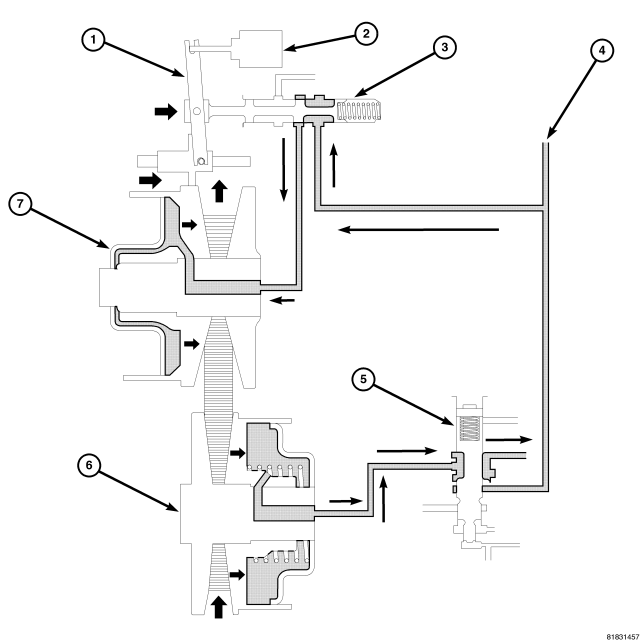
| SHIFT LOW TO HIGH 3 |
| 1 - PULLEY RATIO LINKAGE |
5 - SECONDARY VALVE |
| 2 - STEPPER MOTOR |
6 - SECONDARY PULLEY |
| 3 - RATIO CONTROL VALVE |
7 - PRIMARY PULLEY |
| 4 - LINE PRESSURE |
By applying line pressure to the primary pulley, the sliding element moves to the right direction and the steel belt is pushed outward on the primary pulley.
By actuating the “moving-pulley” of the primary pulley to the right direction, the ratio control valve starts to move to the right direction through the pulley ratio linkage which is driven by the sliding element.
By pulling the steel belt to the primary pulley side, the moving-pulley of the secondary pulley moves to the right side also.
SHIFT LOW TO HIGH - PHASE 4
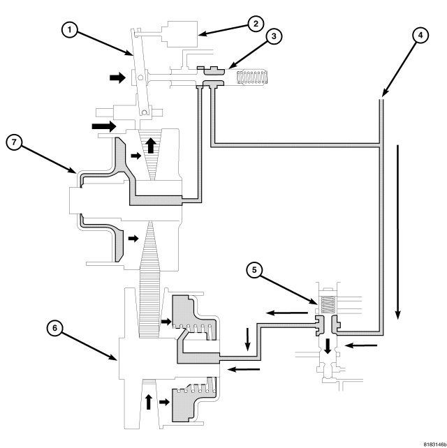
| SHIFT LOW TO HIGH 4 |
| 1 - PULLEY RATIO LINKAGE |
5 - SECONDARY VALVE |
| 2 - STEPPER MOTOR |
6 - SECONDARY PULLEY |
| 3 - RATIO CONTROL VALVE |
7 - PRIMARY PULLEY |
| 4 - LINE PRESSURE |
Additionally, the sliding element of the primary pulley moves to the right direction and the ratio control valve also moves to the right side and closes the line pressure circuit; this is a completion of the shift.
The secondary valve moves downwards to apply the line pressure to the secondary pulley in order to apply clamping force to the steel belt.
SHIFT HIGH TO LOW - PHASE 1
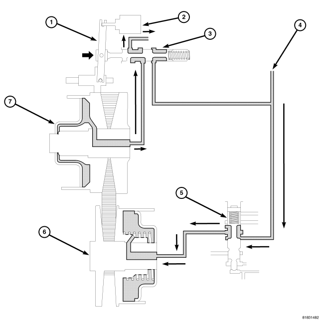
| SHIFTING HIGH TO LOW |
| 1 - PULLEY RATIO LINKAGE |
5 - SECONDARY VALVE |
| 2 - STEPPER MOTOR |
6 - SECONDARY PULLEY |
| 3 - RATIO CONTROL VALVE |
7 - PRIMARY PULLEY |
| 4 - LINE PRESSURE |
The pulley ratio linkage moves to the right direction in the stepper motor. As the ratio control valve which links to the pulley ratio linkage, moves fluid and the primary pulley is drained.
Because the secondary valve is moving downwards, line pressure is maintained in the secondary pulley.
SHIFT HIGH TO LOW - PHASE 2
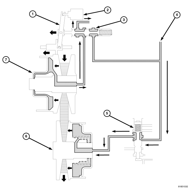
| SHIFTING HIGH TO LOW 2 |
| 1 - PULLEY RATIO LINKAGE |
5 - SECONDARY VALVE |
| 2 - STEPPER MOTOR |
6 - SECONDARY PULLEY |
| 3 - RATIO CONTROL VALVE |
7 - PRIMARY PULLEY |
| 4 - LINE PRESSURE |
The stepper motor (2) first moves to the right which causes the ratio valve (3) to vent oil from the primary movable pulley at a speed that allows some belt clamping to be maintained. As the oil is exhausted, the moveable side of the primary pulley moves to the left allowing the belt to be pulled down into the low ratio position by the constantly maintained line pressure in the secondary pulley. As the primary pulley moveable side moves to the left, the ratio valve is pulled to the left which closes off the oil venting from the primary pulley thereby stopping the ratio change. For each position of the stepper motor, there is a corresponding position of the primary moveable sheave therefore.
SHIFT HIGH TO LOW - PHASE 3
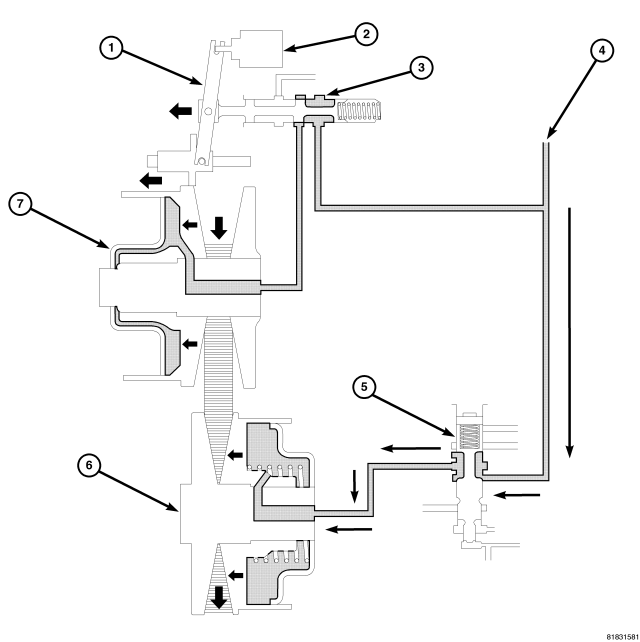
| SHIFTING HIGH TO LOW 3 |
| 1 - PULLEY RATIO LINKAGE |
5 - SECONDARY VALVE |
| 2 - STEPPER MOTOR |
6 - SECONDARY PULLEY |
| 3 - RATIO CONTROL VALVE |
7 - PRIMARY PULLEY |
| 4 - LINE PRESSURE |
Additionally, the moving-pulley of the secondary pulley moves to the left direction and the steel belt is pushed outside. In accordance with this, the sliding element of the primary pulley moves to the left side.
The moving-pulley of the primary pulley moves to the right direction, then the ratio control valve also moves to the left direction and closes the drain circuit; this is a completion of the shift.
REMOVAL
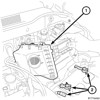
1. Disconnect battery cables (2).
2. Remove air cleaner assembly (1).
3. Remove battery.
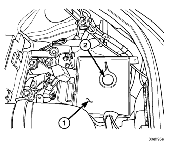
4. Remove battery tray (1).
5. Drain coolant. (Refer to 7 - COOLING - STANDARD PROCEDURE)
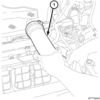
6. Remove inlet air tube (1).
7. Remove vacuum supply lines.
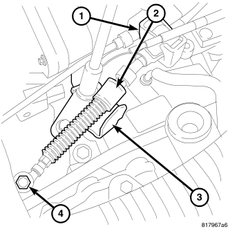
8. Remove the shifter cable (2) and bracket (3).
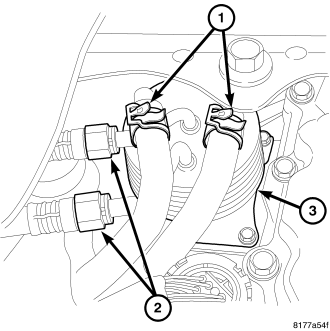
9. Remove coolant lines (2) at CVT fluid cooler.
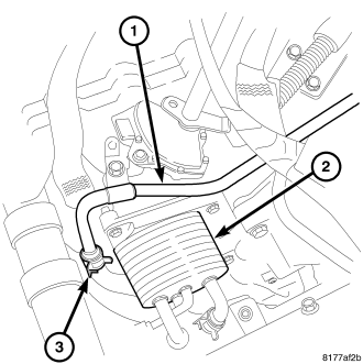
10. Remove heater hose (3) at CVT fluid cooler.
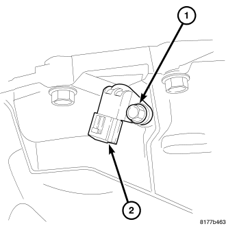
11. Remove the speed sensor connector (1).
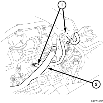
12. Remove the wiring harness from the top of the transmission (2).
13. Remove the transmission vent tube (1).
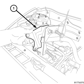
14. Remove the throttle body support bracket (1).
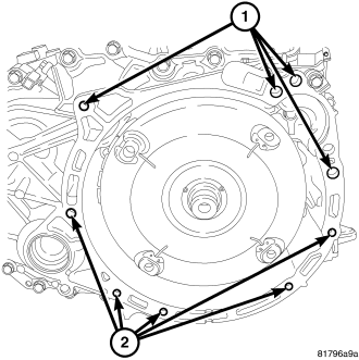
15. Remove the upper bell housing bolts (1).
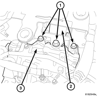
16. Remove the upper transmission mount bolts (1).
17. Remove the upper transmission mount through bolt.
18. Remove the upper transmission mount (2).
19. Raise vehicle on a hoist.
20. Drain transmission fluid.
21. Remove the left front lower splash shield.
22. Remove the right front lower splash shield.
23. Remove lower splash shield (if equipped).
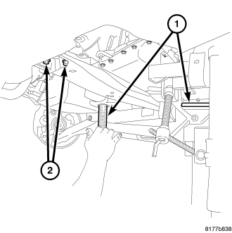
24. Support the transmission with a jack (1).
25. Remove the starter (Refer to 8 - ELECTRICAL/STARTING/STARTER MOTOR - REMOVAL).
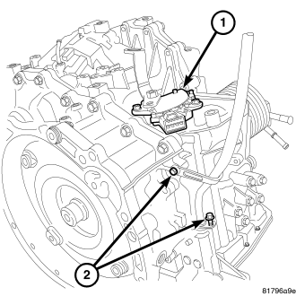
26. Remove the two transmission fill tube bolts (2) and remove the fill tube.
27. Drain the transmission fluid.
28. Remove both front wheels.
29. Remove the right and left halfshafts (Refer to 3 - DIFFERENTIAL & DRIVELINE/HALFSHAFT - REMOVAL).
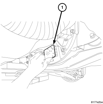
30. Remove inspection cover (1).
31. Mark the torque converter to the flex plate for alignment upon installation.
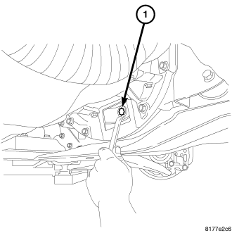
32. Remove torque converter bolts (1).
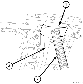
33. Support the engine with a screw jack (2).
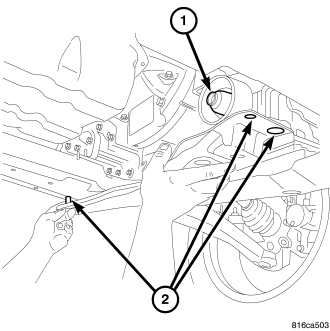
34. Remove the through bolt (1) at the front transmission mount.
35. Remove bolts (2) at the transmission cross member.
36. Remove the transmission cross member.
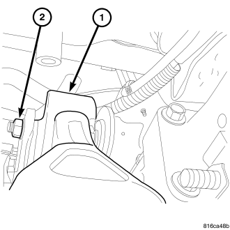
37. Remove the transmission rear mount thorough bolt (2).
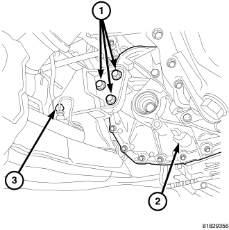
38. Remove the rear mount to transaxle bolts (1).
39. Remove the PTU if equipped (Refer to 21 - TRANSMISSION/TRANSAXLE/POWER TRANSFER UNIT - REMOVAL).
40. Remove the lower transmission bell housing bolts (2).
41. Lower transmission.
DISASSEMBLY
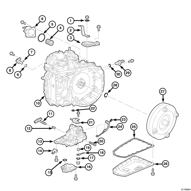
| 1- WASHER | 16 - OIL STRAINER |
| 2 - SHIFT LEVER | 17 - PLAIN WASHER |
| 3 - INHIBITOR SWITCH | 18 - MANUAL LEVER |
| 4 - CVT FLUID FILTER | 19 - BUSHING |
| 5 - O-RING | 20 - MANUAL VALVE |
| 6 - CVT FLUID COOLER | 21 - STEPPER MOTOR |
| 7 - SHIM | 22 - LIP SEAL |
| 8 - OUTPUT SPEED SENSOR | 23 - SNAP RING |
| 9 - O-RING | 24 - VALVE BODY HARNESS |
| 10 - TRANSAXLE | 25 - OIL PAN GASKET |
| 11 - PULLEY RATIO LINKAGE | 26 - OIL PAN |
| 12 - SPRING | 27 - TORQUE CONVERTER |
| 13 - CONTROL VALVE | 28 - O-RING |
| 14 - BRACKET | 29 - INPUT SPEED SENSOR |
| 15 - O-RING | 30 - O-RING |
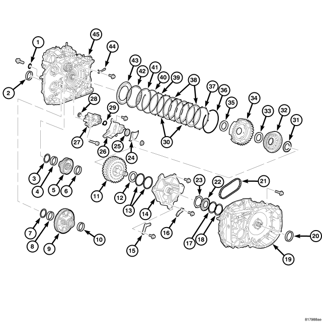
| 1 - O-RING | 24 - BAFFLE PLATE |
| 2 - SIDE OIL SEAL | 25 - DRIVEN SPROCKET (OIL PUMP) |
| 3 - ADJUSTABLE SHIM | 26 - BAFFLE PLATE |
| 4 - OUTER RACE | 27 - OIL PUMP |
| 5 - REDUCTION GEAR ASSEMBLY | 28 - LIP SEAL |
| 6 - OUTER RACE | 29 - SNAP RING |
| 7 - ADJUSTABLE SHIM | 30 - DRIVEN PLATES |
| 8 - OUTER RACE | 31 - NEEDLE BEARING |
| 9 - DIFFERENTIAL ASSEMBLY | 32 - SUN GEAR |
| 10 - OUTER RACE | 33 - NEEDLE BEARING |
| 11 - FORWARD CLUTCH ASSEMBLY | 34 - PLANETARY CARRIER |
| 12 - NEEDLE BEARING | 35 - NEEDLE BEARING |
| 13 - SEAL RING | 36 - SNAP RING |
| 14 - OIL PUMP COVER | 37 - RETAINING PLATE |
| 15 - BAFFLE PLATE | 38 - DRIVEN PLATES |
| 16 - BRACKET | 39 - DISH PLATE |
| 17 - ADJUSTABLE SHIM | 40 - SNAP RING |
| 18 - ADJUSTABLE SHIM | 41 - RETAINING PLATE |
| 19 - CONVERTER HOUSING | 42 - SPRING RETAINER ASSEMBLY |
| 20 - CONVERTER HOUSING OIL SEAL | 43 - REVERSE PLATE PISTON |
| 21 - OIL PUMP CHAIN | 44 - DETENT SPRING |
| 22 - DRIVE SPROCKET | 45 - TRANSAXLE CASE |
| 23 - THRUST WASHER |
1. Refer to the exploded views as necessary when performing the following steps.
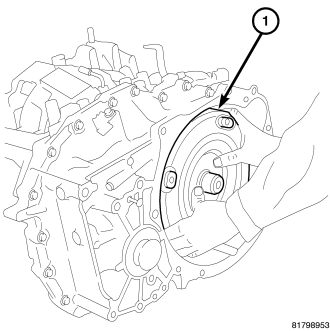
2. Drain the CVT fluid from the transaxle assembly.
3. Remove the power transfer unit assembly and o-ring (4WD only).
4. Remove the torque converter (1) from the transaxle.
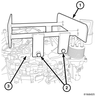
5. Install Transmission Service Stand 9878 (1) to the belt side of the transmission case (3) using the upper transmission mount bolts (2).
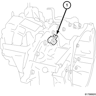
6. Remove the output speed sensor (1) from the converter housing. Remove and discard the o-ring from the output speed sensor.
CAUTION: Set aside and reuse any adjusting shim found between the output speed sensor and the converter housing.
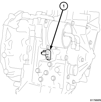
7. Remove the input speed sensor (1) from the transaxle case. Remove and discard the o-ring from the input speed sensor.
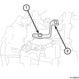
8. Remove the nut (1) holding the shift lever (2) to the manual shaft.
9. Remove the shift lever from the manual shaft.
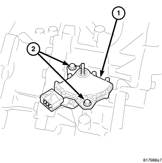
10. Remove the bolts (2) holding the transmission range sensor (TRS) (1) to the transaxle case.
11. Remove the (TRS) transmission range sensor (1) from the transaxle case and the manual shaft.
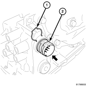
12. Remove the snap ring (1) from the terminal body (2) and press the terminal body into the transaxle case.
CAUTION: Be careful not to cause damage to the terminal body.
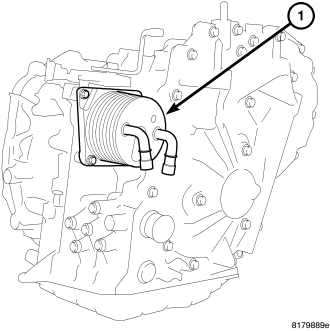
13. Remove CVT fluid cooler (1) from transaxle case. Remove and discard the CVT fluid cooler o-ring.
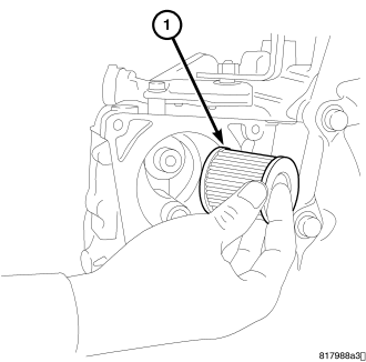
14. Remove the bolts holding the CVT fluid filter to the transaxle case.
15. Remove the CVT fluid filter (1) from the transaxle case.
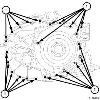
16. Remove the converter housing mounting bolts.
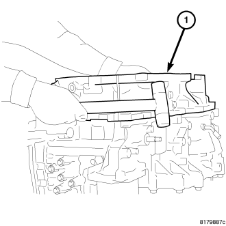
17. Remove the converter housing (1) by tapping with plastic hammer.
CAUTION: There is a possibility that the drive sprocket adjusting shim may be dislodged and fall out.
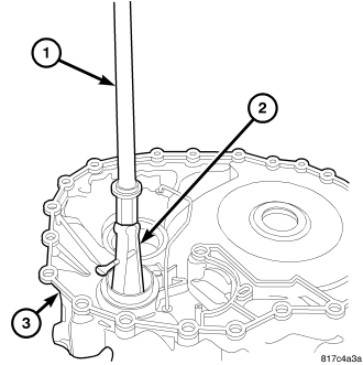
18. Remove outer race of reduction gear bearing (1) from the converter housing using Puller 7794-A and Puller C-637.
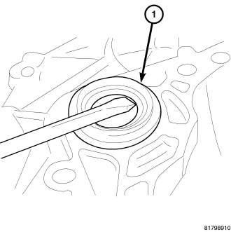
19. Remove differential side oil seal (1) from converter housing using a screwdriver. (2WD)
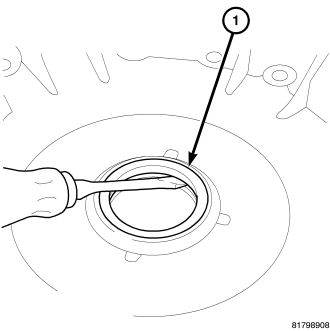
20. Remove converter housing oil seal (1) from converter housing using a screwdriver.
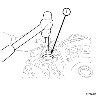
21. Remove outer race (1) of differential side bearing from converter housing using a suitable punch.
CAUTION: When removing the outer race, tap the outer race on both sides evenly. When removing the outer race, do not damage the converter housing.
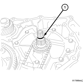
22. Remove and discard the O-ring (1) from the input shaft.
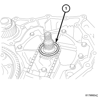
23. Remove the adjusting shim (1) from the drive sprocket, if necessary.
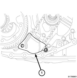
24. Remove the nuts holding the baffle plate (1) to the transaxle.
25. Remove the baffle plate.
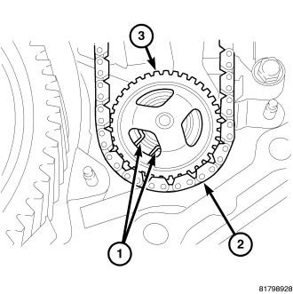
26. Expand the snap ring (1), and remove the driven sprocket (3), the oil pump chain (2), and the drive sprocket.
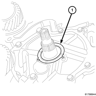
27. Remove the thrust washer (1) from the oil pump cover.
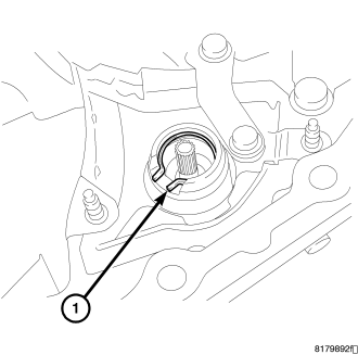
28. Remove the snap ring (1) from the oil pump.
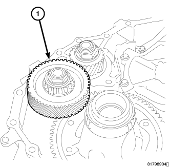
29. Remove the reduction gear assembly (1) from the transaxle case.
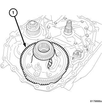
30. Remove the differential assembly (1) from the transaxle case.
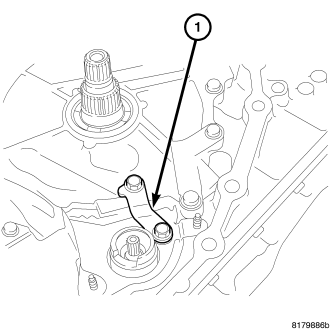
31. Remove the bolts holding the bracket (1) to the oil pump cover and the transaxle.
32. Remove the bracket (1).
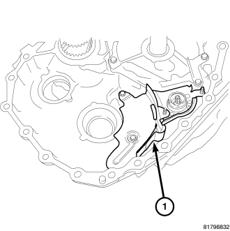
33. Remove the bolts holding the baffle plate (1) to the transaxle.
34. Remove the baffle plate.
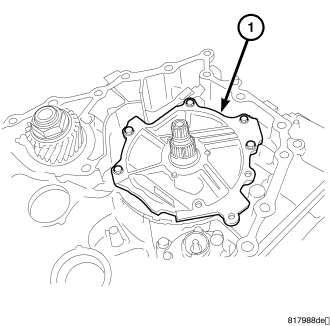
35. Remove the bolts holding the reaction shaft support (1) to the transaxle.
36. Remove the reaction shaft support from the transaxle case.
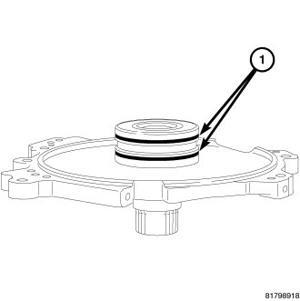
37. Remove and discard the seal rings (1) from the reaction shaft support.
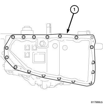
38. Remove the bolts holding the oil pan (1) to the transaxle case.
39. Remove the oil pan from the transaxle case.
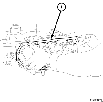
40. Remove the oil pan gasket (1) from the transaxle case.
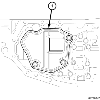
41. Remove the bolts holding the oil strainer (1) to the valve body.
42. Remove the oil strainer.
43. Remove and discard the oil strainer o-ring.
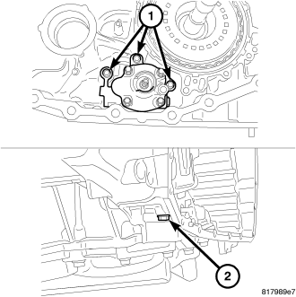
44. Remove the bolt (2) holding the oil pump to the transaxle case from the rear of the transaxle.
45. Remove the bolts (1) holding the oil pump to the transaxle case from inside the transaxle.
46. Remove the oil pump from the transaxle case.
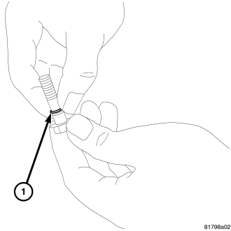
NOTE: One of the oil pump retaining bolts is installed from the outside of the transaxle case into the rear part of the oil pump.
47. Remove and discard the o-ring (1) from the oil pump mounting bolt. (Only on bolt installed from the outside of the transaxle case)
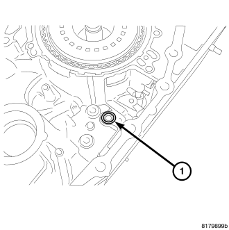
48. Remove and discard the lip seal (1) from the transaxle case.
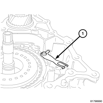
49. Remove the bolt holding the detent spring (1) to the transaxle case.
50. Remove the detente spring from the transaxle case.
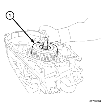
51. Remove the forward clutch assembly (1) from the transaxle case.
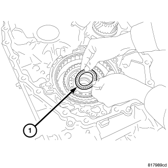
52. Remove needle bearing (1) from forward clutch drum side of the sun gear.
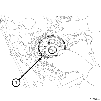
53. Remove the sun gear (1) from the planetary carrier.
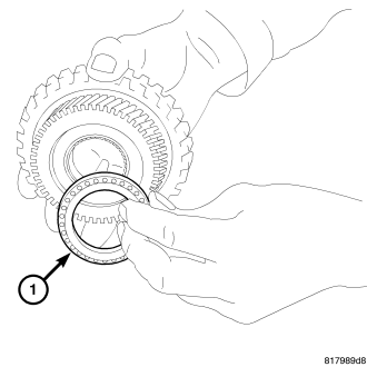
54. Remove the needle bearing (1) from the sun gear.
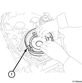
55. Remove the planetary carrier assembly (1) from the transaxle case.
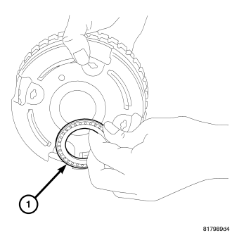
56. Remove the needle bearing (1) from the planetary carrier.
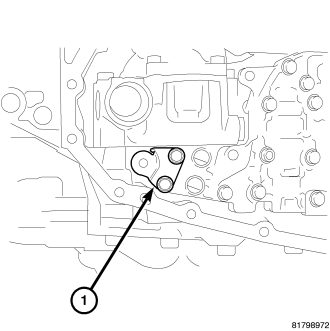
57. Remove the bolts holding the bracket (1) to the valve body assembly.
58. Remove the bracket from the valve body assembly.
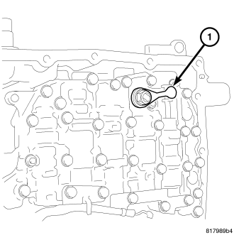
59. Remove the nut holding the manual lever (1) to the manual shaft.
60. Remove the manual lever.
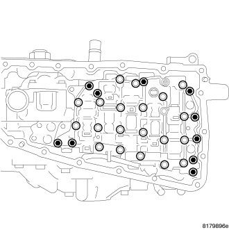
61. Use this picture when removing valve body attaching bolts.
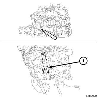
CAUTION: Tilt the valve body assembly away from the transaxle case on the manual shaft side to ease removal. Pay attention to completely remove the terminal body from the transaxle case.
62. Remove the valve body assembly from the transaxle case as follows:
a. Insert a 75 mm (3 in.) long 3 mm (0.118 in.) wide rod or wire into the linkage stopper hole of the valve body assembly to fix the pulley ratio linkage (1).
b. Remove the bolts holding the valve body assembly to the transaxle case.
c. Remove the valve body assembly from the transaxle case.
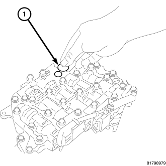
63. Remove and set aside the bushing (1) from the valve body.
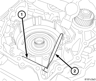
64. Remove the pin at the manual shaft using a punch (2).
65. Remove the manual shaft from case.
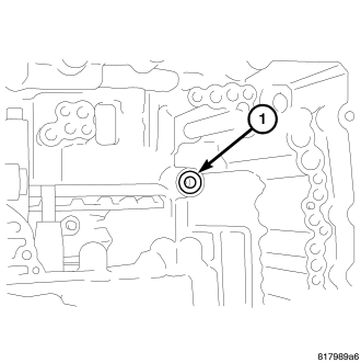
66. Remove and discard the lip seal (1) from the transaxle case.
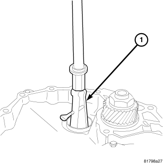
67. Remove outer race (1) of differential side bearing from converter main housing using Puller 9664 and Puller C-637.
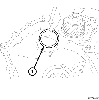
68. Remove the selective shim (1) from the transaxle case.
69. Remove outer race of reduction gear bearing (1) from transaxle case using Puller C-637 and Puller 7794-A.
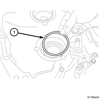
70. Remove the selective shim (1) from the transaxle case.
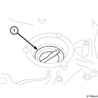
CAUTION: When removing the side oil seal, do not damage the transaxle case.
71. Remove side oil seal (1) from transaxle case using a screwdriver.
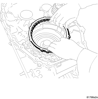
CAUTION: Check if there is damage, deformation, or burning on the surface of any of the drive or driven plates. Check for permanent fatigue of the dish plate, driven plates, retaining plate, snap ring, and the drive plates. Replace all reverse brake components if any of these conditions exist.
72. Remove the reverse brake snap ring using a screwdriver. Then remove the reverse brake retaining plate, the drive plates, the driven plates, and the dish plate from the transaxle case.
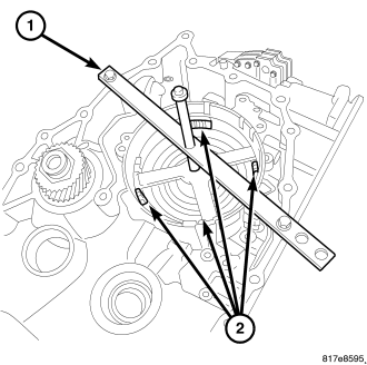
CAUTION: Set the spring compressor right on top of the return spring of the spring retainer assembly. Do not remove the return springs from the spring retainer assembly.
73. Compress the reverse brake return spring using Spring Compressor 5058A (1) and Reverse Piston Compressor 9875. Remove the snap ring (2) from the transaxle case.
74. Remove the retaining plate and the spring retainer assembly.
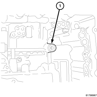
CAUTION: There is a possibility that the reverse brake piston might be stuck if excessive pressure is required to remove.
75. Try removing the reverse brake piston from the transaxle case by hand if unable to remove by hand, apply compressed air to the fluid passage (1). and remove the reverse brake piston from the transaxle case.
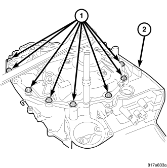
76. Remove the case bolts (1) at the drive belt assembly (2).
NOTE: Pin at pulley sensor stays with drive belt assembly case.
77. Separate drive belt assembly case from main housing.
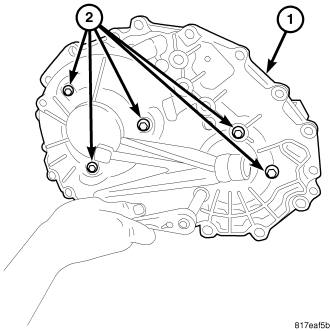
78. Remove the bolts (2) that hold both sheaves to the case (1).
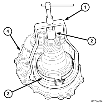
CAUTION: Do not allow the Sheave Compressor 9874 to come in contact with the belt at any time
79. Install the Puller 9874 (1) and Insert 8513A (2) onto the secondary sheave (3).
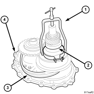
CAUTION: Do not over tighten the compressor tool. Tighten to no more than 7 N·m (50 in. lbs.)
NOTE: The belt is directional, look for an arrow indicating the direction of the belt for installation
80. Compress sheave (2) to the stop.
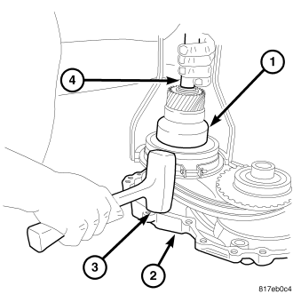
CAUTION: Do not allow the primary sheave to contact the drive surface of the secondary sheave.
NOTE: You may need to lightly tap case while holding secondary sheave.
81. Lift and move the secondary sheave (1) closer to the primary sheave.
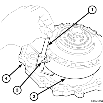
82. Remove the pin (1) from the sheave height sensor (3).
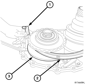
83. Lift the primary sheave (3) enough to remove the sheave height sensor (1).
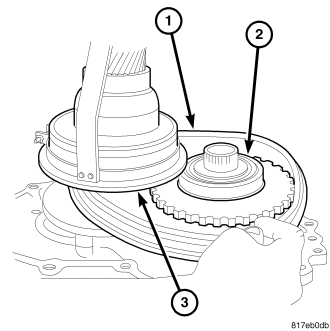
84. Remove the drive belt (1) from both secondary (3) and primary sheaves (2).
85. Remove the secondary sheave.
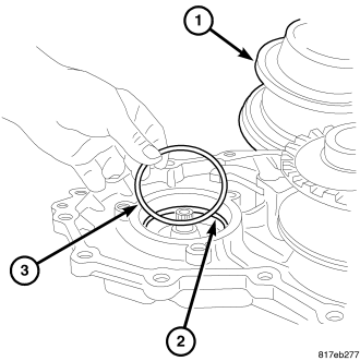
86. Remove the shim (3) under the secondary sheave (1).
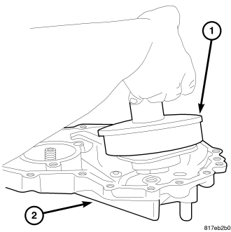
87. Remove the primary sheave.
88. Remove bolts at the park pawl.
89. Remove the park pawl.
ASSEMBLY
| 1- WASHER | 16 - OIL STRAINER |
| 2 - SHIFT LEVER | 17 - PLAIN WASHER |
| 3 - INHIBITOR SWITCH | 18 - MANUAL LEVER |
| 4 - CVT FLUID FILTER | 19 - BUSHING |
| 5 - O-RING | 20 - MANUAL VALVE |
| 6 - CVT FLUID COOLER | 21 - STEPPER MOTOR |
| 7 - SHIM | 22 - LIP SEAL |
| 8 - OUTPUT SPEED SENSOR | 23 - SNAP RING |
| 9 - O-RING | 24 - VALVE BODY HARNESS |
| 10 - TRANSAXLE | 25 - OIL PAN GASKET |
| 11 - PULLEY RATIO LINKAGE | 26 - OIL PAN |
| 12 - SPRING | 27 - TORQUE CONVERTER |
| 13 - CONTROL VALVE | 28 - O-RING |
| 14 - BRACKET | 29 - INPUT SPEED SENSOR |
| 15 - O-RING | 30 - O-RING |
| 1 - O-RING | 24 - BAFFLE PLATE |
| 2 - SIDE OIL SEAL | 25 - DRIVEN SPROCKET (OIL PUMP) |
| 3 - ADJUSTABLE SHIM | 26 - BAFFLE PLATE |
| 4 - OUTER RACE | 27 - OIL PUMP |
| 5 - REDUCTION GEAR ASSEMBLY | 28 - LIP SEAL |
| 6 - OUTER RACE | 29 - SNAP RING |
| 7 - ADJUSTABLE SHIM | 30 - DRIVEN PLATES |
| 8 - OUTER RACE | 31 - NEEDLE BEARING |
| 9 - DIFFERENTIAL ASSEMBLY | 32 - SUN GEAR |
| 10 - OUTER RACE | 33 - NEEDLE BEARING |
| 11 - FORWARD CLUTCH ASSEMBLY | 34 - PLANETARY CARRIER |
| 12 - NEEDLE BEARING | 35 - NEEDLE BEARING |
| 13 - SEAL RING | 36 - SNAP RING |
| 14 - OIL PUMP COVER | 37 - RETAINING PLATE |
| 15 - BAFFLE PLATE | 38 - DRIVEN PLATES |
| 16 - BRACKET | 39 - DISH PLATE |
| 17 - ADJUSTABLE SHIM | 40 - SNAP RING |
| 18 - ADJUSTABLE SHIM | 41 - RETAINING PLATE |
| 19 - CONVERTER HOUSING | 42 - SPRING RETAINER ASSEMBLY |
| 20 - CONVERTER HOUSING OIL SEAL | 43 - REVERSE PLATE PISTON |
| 21 - OIL PUMP CHAIN | 44 - DETENT SPRING |
| 22 - DRIVE SPROCKET | 45 - TRANSAXLE CASE |
| 23 - THRUST WASHER |
1. Refer to the exploded views as necessary when performing the following steps.
2. Install the primary sheave (2) with the sheave height sensor, (3) spring and pin (1) into the belt side case.
3. Install the secondary sheave positioning shim (3) into the belt side cover.
4. Install Puller 9874 (1) and Press Insert 8513 A, (2) onto secondary sheave.
5. Move the secondary sheave (3) close enough to the primary (2) sheave to allow the drive belt (1) to be put around both secondary and primary sheaves.
NOTE: The drive belt is directional and will need to be installed in the same direction as noted in disassembly. if installed incorrectly failure will occur.
6. Install the drive belt (1).
CAUTION: Do not over tighten the compressor tool. Tighten to no more than 7 N·m (50 in. lbs.).
7. Compress the secondary (3) sheave to the stop.
8. Install the drive belt (1) around both secondary (3) and primary (2) sheaves.
9. Install the primary sheave into place.
10. Remove Puller 9874 and Press Insert 8513A from the primary sheave.
11. Install the bolts (2) that hold both sheaves to the case (1).
CAUTION: Remove moisture, oil, and used sealant from the sealant application surface. Make sure that the starting point and the ending point are between two bolt holes.
12. Apply Loctite 509 sealer onto the belt side of the transaxle case.
13. Install the belt side assembly to the transaxle case.
14. Install the case bolts (1) to hold the drive belt assembly (2) to the transaxle. tighten to 45 N·m (33 ft.lbs.).
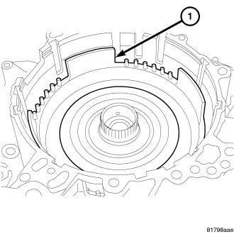
CAUTION: Inspect the reverse brake piston and, if damaged, replace it before installation. Apply CVT fluid to the seal when installing the reverse brake piston.
NOTE: Rotate reverse brake piston into place
15. Rotate and install the reverse brake piston (1) into the transaxle case.
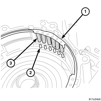
16. Align the return springs (3) of the spring retainer assembly (1) to the locating posts (2) of the reverse clutch piston.
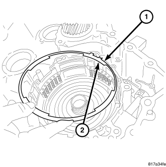
NOTE: There is a notch in the retaining plate that points to the top of the case.
17. Install the retaining plate (1) into the transaxle case with the notch on the plate to the top (2).
CAUTION: Set the spring compressor on top of the spring retainer assembly.
18. Compress the reverse brake return spring using Spring Compressor 5058 A (1) and Reverse Piston Compressor 9875 and install the snap ring into the transaxle case using a screwdriver.
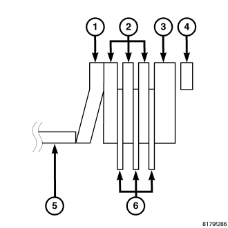
19. Install the dish plate (1) with the convex side down onto the reverse brake piston.
20. Install driven plate (2) and then a drive plate (6) until all the driven and drive plates are installed.
21. Install the retaining plate (3) into the reverse brake assembly.
22. Install the reverse brake snap ring (4) into the transaxle case.
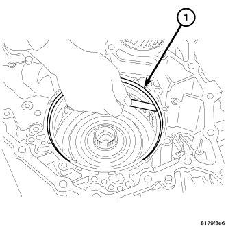
CAUTION: When conducting measurements, measure two or more places and calculate the average value.
23. Measure the clearance between the snap ring and the retaining plate (1). The correct clutch clearance is 1.2-1.5 mm (0.047-0.059 in.). If the clutch clearance is not within specifications, measure the existing retaining plate and select the correct retaining plate.
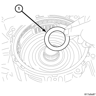
CAUTION: Apply Vaseline or assembly lube when installing the needle bearing. Be careful to verify correct orientation of the needle bearing when installing it.
NOTE: The inner race will need to face down.
24. Install the needle bearing (1) onto the reverse brake piston. Check for the direction of the needle bearing while installing.
NOTE: The inner race will need to face down
25. Install the planetary carrier assembly (1) onto the reverse brake.
CAUTION: Apply Vaseline or assembly lube when installing the needle bearing. Be careful to verify correct orientation of the needle bearing when installing it.
26. Install the needle bearing (1) onto the primary pulley side of the sun gear.
27. Install the sun gear (1) onto the planetary carrier.
CAUTION: Apply Vaseline or assembly lube when installing the needle bearing. Be careful to verify correct orientation of the needle bearing when installing it.
NOTE: The inner race will need to face up.
28. Install the needle bearing (1) on the forward clutch drum side of the sun gear.
29. Install the forward clutch assembly (1) into the transaxle case.
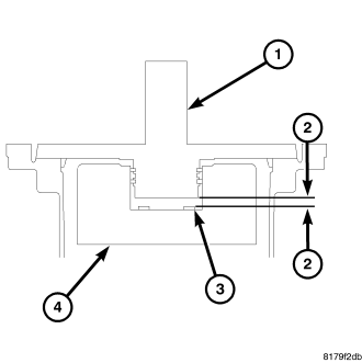
30. Measure the total end play (2) in the following steps. Total end play should be 0.25 - 0.55 mm (0.010 - 0.022 in).
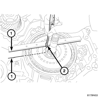
NOTE: Gauge bar 6311 can be used for doing the following measurement.
31. Measure the distance (1) from the oil pump cover installation surface of the transaxle case to the needle bearing installation surface of the forward clutch drum. Call this measurement one.
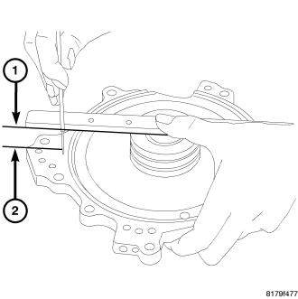
NOTE: Gauge bar 6311 can be used for doing the following measurement.
32. Measure the distance (1 to 2) as shown. Call this measurement two.
33. Calculate the bearing thickness required to achieve the necessary end play with the following formula. The bearing thickness is equal to measurement one, minus measurement two minus, the nominal end play (0.40 mm or 0.016 “in).
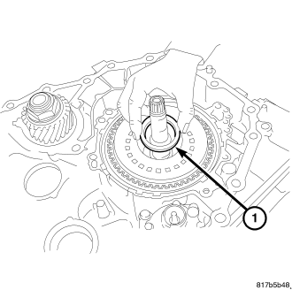
CAUTION: Apply Vaseline or assembly lube when installing the needle bearing. Be careful to verify correct orientation of the needle bearing when installing it.
34. Install the selected needle bearing (1) on the forward clutch assembly.
35. Install the detent spring (1) onto the transaxle case. Install the bolt to hold the detent spring to the transaxle case and tighten the mounting bolt to 7 N·m (61 in.lbs.).
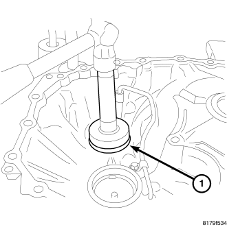
36. Install the outer race of the differential bearing (1) into the converter housing using Installer 9668 and Installer 4628 on 4WD, use Installer 4628 on 2WD and Driver Handle C-4171.
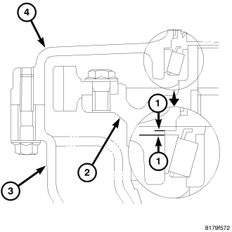
| 1 - PRELOAD SHIM |
| 2 - DIFFERENTIAL ASSEMBLY |
| 3 - TRANSAXLE CASE |
| 4 - CONVERTER HOUSING |
CAUTION: When adjusting the preload, apply CVT fluid on the bearing to make it roll smoothly. When conducting measurements, measure two or more places and calculate the average value.
37. Measure for the differential preload shim (1) in the following steps. Refer to the graphic as necessary when performing the steps.
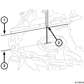
NOTE: Gauge bar 6311 can be used for doing the following measurement.
38. The required differential preload is 0.17 to 0.29 mm (0.007 0.011 to in).
39. Measure the distance (1-3) from the edge of the transaxle case to the select shim installation surface. This is differential measurement one.
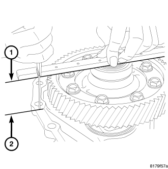
NOTE: Gauge bar 6311 can be used for doing the following measurement.
40. Install the differential assembly on the converter case and measure the distance (differential measurement two) (1-2) from the differential hub to the surface of the converter housing.
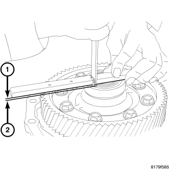
NOTE: Gauge bar 6311 can be used for doing the following measurement.
41. Install the outer race for the differential side bearing and measure the distance (differential measurement three) (1-2) from the differential case to the outer race of the differential side bearing.
42. The thickness of the required select shim is calculated as follows: differential measurement one, minus differential measurement two, plus differential measurement three, plus 0.23 mm (0.009 in).
CAUTION: Do not re-use the select shim.
43. Install the chosen select shim (1) into the transaxle case.
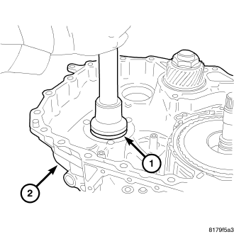
44. Install the outer race (1) of the differential bearing on the transaxle case using the Installer D-129 and Drive Handle C-4171.
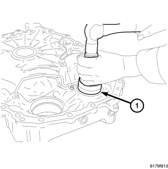
45. Install the outer race (1) of the reduction gear bearing into the converter housing using Installer C-4628 and Driver Handle C-4171.
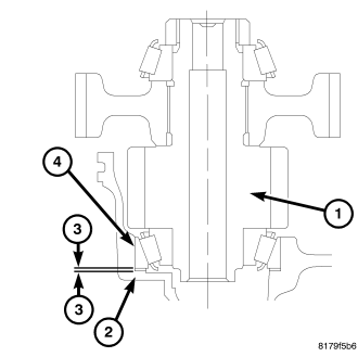
| 1 - REDUCTION GEAR |
| 2 - TRANSAXLE CASE |
| 3 - PRELOAD SHIM |
| 4 - BEARING OUTER RACE |
46. The required preload on the reduction gear assembly is 0.13-0.19 mm (0.005-0.0075 in). Measure for the required preload shim (3) as follows:
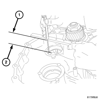
NOTE: Gauge bar 6311 can be used for doing the following measurement.
47. Measure the distance (reduction assembly measurement one) (1-2) from the edge of the transaxle case to the select shim installation surface.
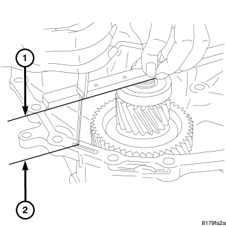
NOTE: Gauge bar 6311 can be used for doing the following measurement.
48. Install the reduction gear assembly on the converter housing and measure the distance (reduction assembly measurement two) (1-2) from the top of the reduction gear assembly to the edge of the converter housing.
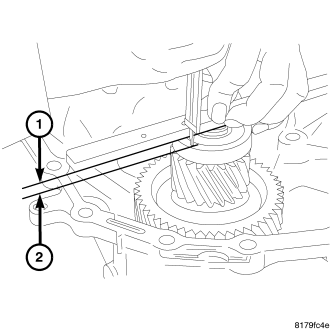
CAUTION: When adjusting the preload, apply CVT fluid on the bearing to make it roll smoothly. When conducting measurements, measure two or more places and calculate the average value.
NOTE: Gauge bar 6311 can be used for doing the following measurement.
49. Install the outer race of the reduction gear bearing and measure the distance (reduction assembly measurement three) (1-2) from the top of the reduction gear assembly to the outer race of the reduction gear bearing.
50. The thickness of the required select shim is calculated as follows: reduction assembly measurement one, minus reduction assembly measurement two, plus reduction assembly measurement three, plus 0.16 mm (0.006 in).
CAUTION: Do not re-use the select shim.
51. Install the chosen select shim (1) into the transaxle case.
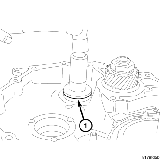
52. Install the outer race (1) of the reduction gear bearing on the transaxle case using Installer C-4628 and Driver Handle C-4171.
CAUTION: Do not re-use the lip seal. Apply CVT fluid when installing the lip seal.
53. Install the new lip seal (1) on the transaxle case.
CAUTION: Do not re-use the o-ring. Apply CVT fluid when installing the O-ring.
54. Install the new o-ring (1) onto the oil pump mounting bolts. (Only for bolts installed from the outside of the transaxle case).
NOTE: One of the oil pump retaining bolts is installed from the outside of the transaxle case in the rear part of the oil pump.
55. Install the oil pump on the transaxle case. Install and tighten the mounting bolts (1) to 19 N·m (14 ft. lbs.) Install and torque the mounting bolt (2) to 28 N·m (20 ft. lbs.).
CAUTION: Do not re-use the lip seal. Apply CVT fluid when installing the lip seal.
56. Install the new lip seal (1) into the transaxle case.
57. Install the manual shaft (1) into the case.
58. install the pin at the manual shaft using a punch (2)
59. To install the valve body assembly on to the transaxle case, insert a 75 mm (3 in.) long 3 mm (0.118 in.) wide rod or wire into the linkage stopper hole of the valve body assembly to set the pulley ratio linkage (1) in position.
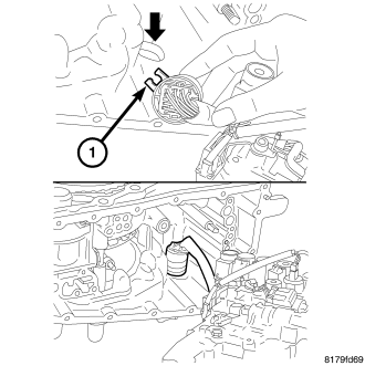
60. Position the locating tab (1) of the terminal body and install the terminal body into the transaxle case.
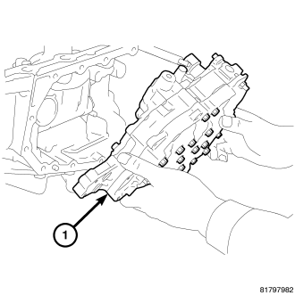
61. Install the valve body assembly (1) up from the bottom side and install it into the transaxle case.
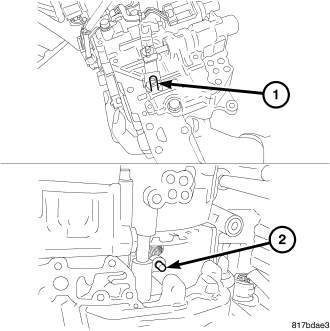
62. Align the notch (1) of the pulley ratio linkage with the sheave position sensor (2).
CAUTION: Apply CVT fluid when installing the bushing.
63. Install the bushing (1) into the valve body assembly.
64. Tighten the mounting bolts of the valve body assembly to 8 N·m (70 in. lbs).
65. Install the manual lever (1) onto the manual shaft. Install and tighten the mounting nut to 22 N·m 194 in. lb.
66. Install the bracket (1) onto the valve body assembly. Install and tighten the mounting bolts to 8 N·m (70 in. lbs.).
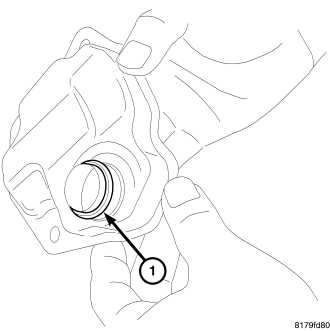
CAUTION: Do not re-use the o-ring. Apply CVT fluid when installing the o-ring.
67. Install the new o-ring (1) onto the new oil strainer.
68. Install the new oil strainer (1) onto the valve body assembly. Install and tighten the mounting bolts to 8 N·m (70 in. bs.).
CAUTION: Do not re-use the oil pan gasket. Remove any moisture, oil, and used gasket material from the surface where the new gasket is to be installed. When installing the oil pan gasket, align the dowel pin with the dowel pin hole in the oil pan gasket.
69. Install the oil pan gasket (1) onto the transaxle case.
CAUTION: When installing the oil pan, align the dowel pin of the transaxle case with the dowel pin hole of the oil pan.
70. Install the oil pan on the transaxle case (1). Install and tighten the mounting bolts to 8 N·m (70 in. lbs.).
71. Install the snap ring (1) onto the terminal body.
CAUTION: Do not re-use the seal rings. Apply Vaseline or assembly lube when installing the seal rings.
72. Install the new seal rings (1) onto the reaction shaft support.
73. Install the reaction shaft support (1) onto the transaxle case temporarily with the mounting bolts.
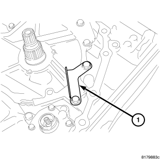
74. Install the baffle plate (1) temporarily with the mounting bolts.
75. Install the baffle plate (1). Install and tighten the mounting bolts to 6 N·m (52 in. lbs.).
76. Install the bracket (1) as shown. Tighten the mounting bolts of the oil pump cover, baffle plate, and brackets to 26 N·m (19 in. lbs.).
77. Install the snap ring (1) into the oil pump.
CAUTION: Be sure to align the pawl of the thrust washer with the alignment hole of the oil pump cover. Apply Vaseline or assembly lube when installing the thrust washer.
78. Install the thrust washer (1) onto the oil pump cover.
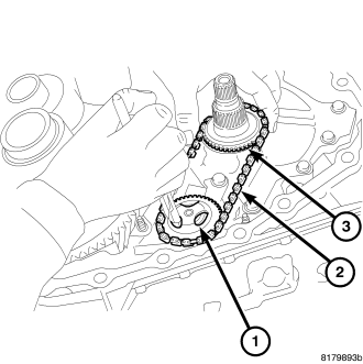
CAUTION: When necessary to replace any of the driven sprocket, oil pump chain, or drive sprocket, replace all components as a matched set. Pull the driven sprocket up softly and check that the driven sprocket is securely installed.
79. Expand the snap ring (1).
80. Install the driven sprocket, oil pump chain (2) and drive sprocket (3).
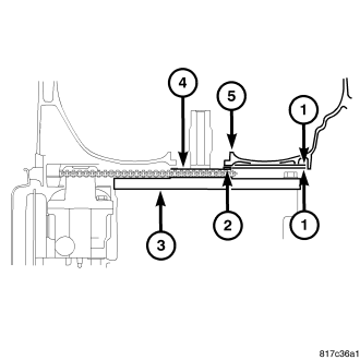
81. The required clearance for the oil pump drive sprocket is 0.10-0.23 mm (0.004-0.009 in.). Measure the clearance (1) between the oil pump drive sprocket (4) and the converter housing (5) in the following procedure:
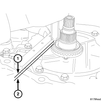
NOTE: Gauge bar 6311 can be used for doing the following measurement.
82. Measure the distance (1-2) from the edge of the transaxle case to the select shim installation surface of the drive sprocket. This is the oil pump drive sprocket measurement one.
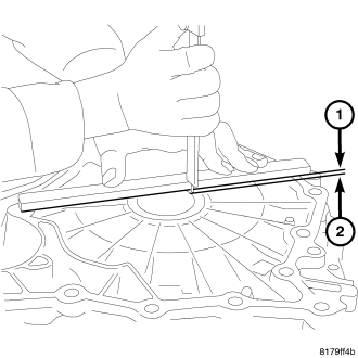
NOTE: Gauge bar 6311 can be used for doing the following measurement.
83. Measure the distance (1-2) from the edge of the converter housing to the surface touching the select shim contact surface. This is the oil pump drive sprocket measurement two.
84. Calculate the thickness of the required select shim with the following formula: The select shim is equal to the oil pump drive sprocket measurement one, plus the oil pump drive sprocket measurement two, minus 0.16 mm (0.0065 in.).
85. Install the chosen select shim (1) onto the drive sprocket.
86. Install the baffle plate (1) over the oil pump driven sprocket. Install and tighten the mounting nut to 6 N·m (52 in. lbs.).
CAUTION: Do not re-use the o-ring. Apply CVT fluid when installing the o-ring.
87. Install the new o-ring (1) onto the input shaft.
88. Install the differential assembly (1) into the transaxle case.
89. Install the reduction gear assembly (1) into the transaxle case.
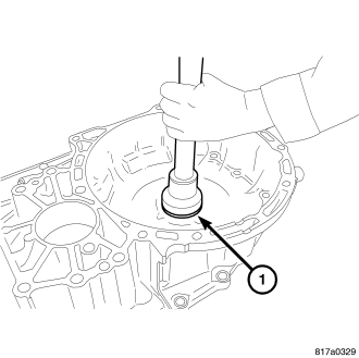
CAUTION: Do not re-use the converter housing oil seal (1). Apply CVT fluid when installing the converter housing oil seal (1).
90. Install the converter housing oil seal (1) into the converter housing with Installer 9858.
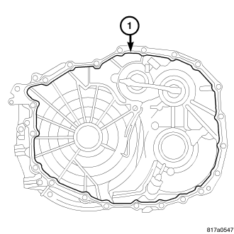
91. Apply MOPAR gasket sealer (1) on the converter housing installation surface of the transaxle case.
CAUTION: Remove moisture, oil, and used sealant from the sealant application surface. Make sure that the starting point and the ending point are between two bolt holes.
92. Install the converter housing on the transaxle case and tighten the bolts to 45 N·m (33 ft. lbs.).
93. Install the transmission range sensor (TRS) (1) over the manual shaft and onto the transaxle case.
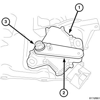
CAUTION: Do not re-use the TRS transmission range sensor.
94. Put the manual shaft in the N position (3). Install Alignment Tool 9876 (2) and adjust the position of the TRS (1).
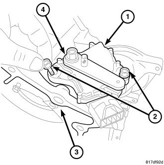
95. Install and tighten the mounting bolts of the TRS to 6 N·m (49 in. lbs.).
96. Remove the TRS alignment tool from the TRS.
97. Install the shift lever (1) onto the manual shaft. Install and tighten the mounting nut to 17 N·m (150 in. lbs.).
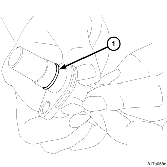
CAUTION: Do not re-use the o-ring. Apply CVT fluid when installing the o-ring.
98. Install the o-ring (1) onto the input speed sensor.
99. Install the input speed sensor (1) into the transaxle case. Install and tighten the mounting bolt to 6 N·m (52 in. lbs.).
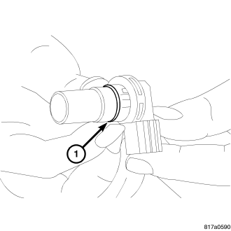
CAUTION: Do not re-use the o-ring. Apply CVT fluid when installing the o-ring.
100. Install the new o-ring (1) onto the output speed sensor.
CAUTION: Be sure to install the select shim between the secondary speed sensor and the converter housing before installing the secondary speed sensor.
101. Install the output speed sensor (1) into the converter housing. Install and tighten the mounting bolt to 6 N·m (52 in lbs.).
CAUTION: Apply CVT fluid on the seal part when installing the CVT fluid filter.
102. Install the CVT fluid filter (1) into the transaxle case.
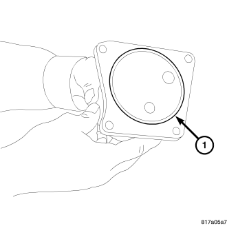
CAUTION: Do not re-use the o-ring. Apply CVT fluid when installing the o-ring.
103. Install the new o-ring (1) onto the CVT fluid filter.
104. Install the CVT fluid cooler (1) onto the transaxle case. Install and tighten the mounting bolts to 4 N·m (37 in .lbs.).
105. Remove the Transmission Service Stand 9878 (1) from the Belt side of the transmission case.
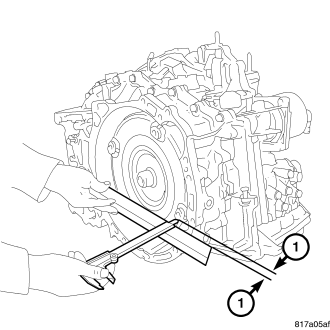
NOTE: Gauge bar 6311 can be used for doing the following measurement.
NOTE: When conducting measurements, measure two or more places and calculate the average value.
106. Install the torque converter on the transaxle and measure the dimension (1) to see if it is at least 13 mm. If the measurement is less than 13 mm, the torque converter is not fully installed.
NOTE: Use the designated brand of CVT fluid. Use of other brands of CVT fluid other than the designated brand will deteriorate the driveability and the durability of the CVT, and will cause damage to the CVT.
107. Fill the transaxle with CVT fluid. (Refer to 21 - TRANSMISSION/TRANSAXLE/AUTOMATIC - CVT/FLUID - STANDARD PROCEDURE)
INSTALLATION
NOTE: Refer to the following table when the Transmission Control Module (TCM) and/or transaxle has been replaced to determine if the TCM memory must be erased.
| TCM | Transaxle | Erase Memory? |
| New Module | Not Replaced | Not Required |
| Not Replaced | Replaced | Relearn Required
(Refer to 8 - ELECTRICAL/ELECTRONIC CONTROL MODULES/TRANSMISSION CONTROL MODULE -
STANDARD PROCEDURE) |
| Replaced With Used Module | N/A |
NOTE: Verify that both dowel pins are present in the engine before installing the transmission.
1. Install the transmission cooler lines (1, 2).
2. Install the lower transmission bell housing bolts (2) and tighten to 48 N·m (35 ft. lbs.).
3. Raise the transmission using a screw jack (2).
4. Install the transmission crossmember and bolts, (2) tighten to 75 N·m (55 ft lbs.).
5. Install the through bolt at the front transmission mount (1) and tighten to 75 N·m (55 ft lbs.).
6. Install rear mount through bolt (1) and tighten bolt to 75 N·m (55 ft lbs.).
7. Install rear mount to transaxle and tighten bolts (1) to 75 N·m (55 ft lbs.).
8. Install new tighten converter bolts (1) and torque to 48 N·m (35 ft. lbs.).
9. Install cover at torque converter (1).
10. Install the PTU if equipped (Refer to 21 - TRANSMISSION/TRANSAXLE/POWER TRANSFER UNIT - INSTALLATION).
11. Install the right front lower splash shield.
12. Install the left front lower splash shield.
13. Install left half and right half shafts to the transaxle (Refer to 3 - DIFFERENTIAL & DRIVELINE/HALF SHAFT - INSTALLATION).
14. Install both front wheels (Refer to 22 - TIRES/WHEELS - REMOVAL) .
15. Lower hoist.
16. Install upper bell housing bolts (1) and tighten to 48 N·m (35 ft. lbs.).
17. Install the upper mount bolts and tighten to 75 N·m (55 ft lbs.).
18. Install the upper mount through bolt and tighten 75 N·m (55 ft lbs.).
19. Install the throttle body support bracket (1) and tighten to 11 N·m (105 in. lbs.).
20. Connect the transmission vent tube (1).
21. Install the heater hose at transmission cooler tube (3).
22. Connect coolant lines at transmission cooler.
23. Install the shifter cable (1) and bracket (2) tighten to 11 N·m (105 in. lbs.).
24. Install the vacuum supply lines.
25. Install intake air tube (1).
26. Fill engine coolant (Refer to 7 - COOLING - STANDARD PROCEDURE) .
27. Install the battery tray (1).
28. Install the battery.
29. Install the air cleaner assembly (1).
30. Connect battery cables (2).
31. Install the transmission fill tube (1) tighten bolt to 9 N·m (79 in. lbs.).
32. Fill the transmission with fluid to the correct level.
CAUTION: Use only MOPAR ® CVTF +4, use of any other type of automatic transmission fluid may cause damage to the CVT.
33. Road test vehicle and inspect for leaks.
SPECIFICATIONS
DESCRIPTION |
SPECIFICATION |
| Forward clutch |
1.2-1.5 mm (0.047-0.059 in.) |
| Total end play |
0.25 - 0.55 mm (0.010 - 0.022 in) |
| Required differential preload |
0.17 to 0.29 mm (0.007 to 0.011 in) |
| Required preload, Reduction gear |
0.13-0.19 mm (0.005-0.0075 in) |
| Reduction Assembly required select shim |
Reduction assembly measurement , minus reduction assembly measurement, plus reduction assembly measurement, plus 0.16 mm (0.006 in). |
| Required clearance, Oil pump drive sprocket |
0.10-0.23 mm (0.004-0.009 in.) The select shim is equal to the oil pump drive sprocket measurement one plus the oil pump drive sprocket measurement, two minus 0.16 mm (0.0065 in.). |
| Torque converter installed depth |
at least 13 mm |
DESCRIPTION |
N-m |
Ft. Lbs. |
In. Lbs. |
| bolts, drive belt assembly - to - transaxle case |
45 |
33 |
- |
| Bolt, Detent spring to case |
7 |
- |
61 |
| Bolts, oil pump - to - transaxle case |
19 |
14 |
168 |
| Bolt, oil pump - to - transaxle case (outside ) |
28 |
20 |
247 |
| Bolts, Valve body assembly - to - case |
8 |
- |
70 |
| Nut, Valve body manual lever - to - manual shaft |
22 |
16 |
194 |
| Bolts, Oil strainer to valve body |
8 |
- |
70 |
| Bolts, oil pan - to - transaxle case |
8 |
- |
70 |
| Bolts, baffle plate |
6 |
- |
52 |
| Bolts, oil pump cover |
26 |
19 |
230 |
| Bolts, Bracket oil pump cover - to oil pump |
26 |
19 |
230 |
| Bolts, Baffle plate |
26 |
19 |
230 |
| Bolts, Baffle plate at oil pump driven sprocket |
6 |
- |
52 |
| Bolts, Converter housing - to - transaxle case |
45 |
33 |
398 |
| Bolts, TRS |
6 |
- |
49 |
| Nut, Shift lever to manual shaft |
17 |
13 |
150 |
| Bolt, Speed input sensor - to - transaxle case |
6 |
- |
52 |
| Bolt, Speed output sensor - to - transaxle case |
6 |
- |
52 |
| Bolts, Fluid cooler - to - transaxle case |
4 |
- |
37 |
| Bolts, transmission bell housing - to - engine |
48 |
35 |
- |
| Bolts, Transmission crossmember |
75 |
55 |
- |
| Nut, Rear mount through bolt |
75 |
55 |
- |
| Bolts, Rear mount to transaxle |
75 |
55 |
- |
| Bolts, Torque converter |
48 |
35 |
- |
| Bolts, Upper transmission mount |
75 |
55 |
- |
| Bolts, PTU support bracket |
68 |
50 |
- |
| bolt, Catalytic Converter Support Bracket |
28 |
- |
250 |
| Nut, Upper mount through bolt |
75 |
55 |
- |
| Bolts, Throttle body support bracket |
11 |
- |
105 |
| Nut, Shifter cable |
11 |
- |
105 |
| Bolts, Transmission fill tube |
9 |
- |
79 |
| Nut, Reduction gear |
250 |
185 |
- |
| Bolts, Shifter - to - floor |
70 |
52 |
- |
| Bolts, Bracket to Valve Body |
8 |
70 |
- |