| Last Modified: 11-27-2007 | 1.6 A | |
| Service Category: Engine/Hybrid System | Section: Engine Mechanical | |
| Model Year: 2008 | Model: LX570 | Doc ID: RM0000030XO004X |
| Title: 3UR-FE ENGINE MECHANICAL: ENGINE UNIT: DISASSEMBLY (2008 LX570) | ||
DISASSEMBLY
1. REMOVE OIL PRESSURE SENDER GAUGE ASSEMBLY

2. REMOVE OIL FILTER ELEMENT
3. REMOVE NO. 1 OIL COOLER BRACKET (w/ Oil Cooler)
4. REMOVE OIL FILTER BRACKET (w/ Oil Cooler)
5. REMOVE OIL FILTER BRACKET (w/o Oil Cooler)
6. REMOVE OIL FILLER CAP SUB-ASSEMBLY
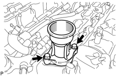
7. REMOVE OIL FILLER CAP HOUSING
|
(a) Remove the 2 bolts, filler cap housing and gasket. |
8. REMOVE SPARK PLUG
(a) Using a 16 mm plug wrench, remove the 8 spark plugs.
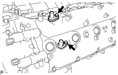
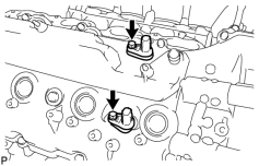
9. REMOVE VVT SENSOR
|
(a) LH: Remove the 2 bolts and 2 VVT sensors. |
|
(b) RH: Remove the 2 bolts and 2 VVT sensors. |
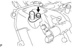
10. REMOVE CAMSHAFT POSITION SENSOR
|
(a) Remove the bolt and camshaft position sensor. |
11. REMOVE CRANK POSITION SENSOR PROTECTOR
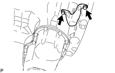
(a) Remove the 2 bolts and sensor protector.
12. REMOVE CRANKSHAFT POSITION SENSOR
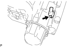
|
(a) Remove the bolt and crankshaft position sensor. |
13. REMOVE CAMSHAFT OIL CONTROL VALVE ASSEMBLY
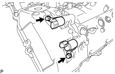
|
(a) LH: Remove the 2 bolts and 2 oil control valves. |
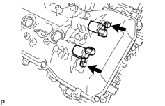
|
(b) RH: Remove the 2 bolts and 2 oil control valves. |
14. REMOVE WATER PUMP PULLEY
15. REMOVE NO. 1 IDLER PULLEY SUB-ASSEMBLY
16. REMOVE FLUID COUPLING BRACKET
17. REMOVE V-RIBBED BELT TENSIONER ASSEMBLY
18. REMOVE CYLINDER HEAD COVER SUB-ASSEMBLY LH
19. REMOVE CYLINDER HEAD COVER SUB-ASSEMBLY RH
20. REMOVE OIL CONTROL VALVE FILTER
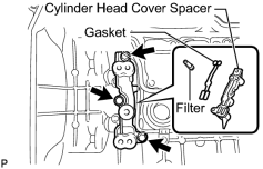
(a) LH:
Remove the 3 bolts, cylinder head cover spacer, gasket and filter.
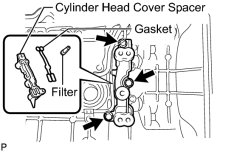
|
(b) RH: Remove the 3 bolts, cylinder head cover spacer, gasket and filter. |
21. REMOVE SPARK PLUG TUBE GASKET
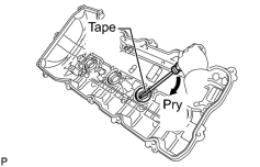
(a) Bend the 4 ventilation baffle plate claws on the cylinder head cover to an angle of 90° or more.
(b) Using a screwdriver, pry out the gaskets.
HINT:
Tape the screwdriver tip before use.
NOTICE:
- Be careful not to damage the cylinder head cover.
- Be careful not to damage the gasket when removing it, as the removed gasket needs to be used when installing a new one.
22. REMOVE CRANKSHAFT PULLEY
23. REMOVE WATER PUMP ASSEMBLY
24. REMOVE TIMING CHAIN COVER SUB-ASSEMBLY
25. REMOVE WATER INLET PIPE
26. REMOVE FRONT CRANKSHAFT OIL SEAL
|
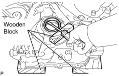
(a) Place the timing chain cover on wooden blocks. |
(b) Using a screwdriver and wooden block, pry out the oil seal.
HINT:
Tape the screwdriver tip before use.
NOTICE:
Do not damage the surface of the oil seal press fit hole.
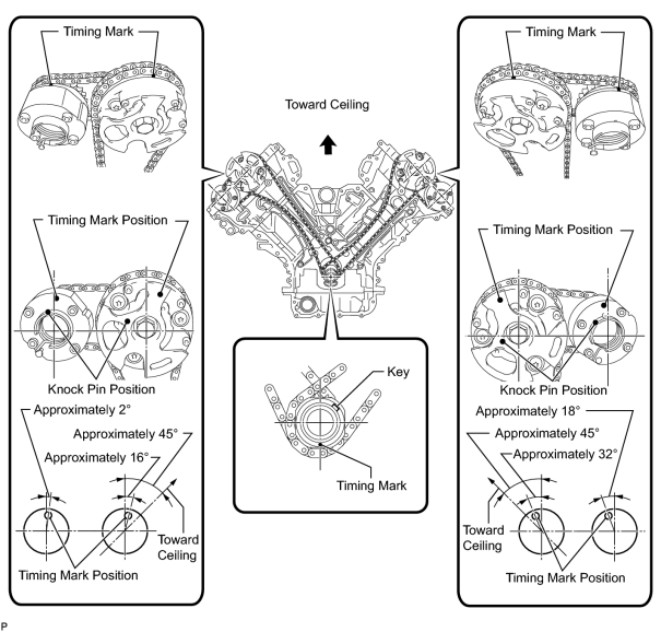
27. SET NO. 1 CYLINDER TO TDC/COMPRESSION
(a) Temporarily install the crankshaft pulley bolt.
(b) Rotate the crankshaft clockwise so that the timing marks on the crankshaft timing sprocket and camshaft timing gears are as shown in the illustration.
HINT:
If the timing marks do not align, rotate the crankshaft clockwise again and align the timing marks.
28. REMOVE NO. 1 CHAIN TENSIONER ASSEMBLY LH
|
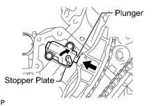
(a) Move the stopper plate clockwise to release the lock, and push the plunger deep into the tensioner. |
|
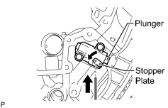
(b) Move the stopper plate counterclockwise to set the lock, and insert a hexagon wrench into the stopper plate hole. |
|
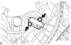
(c) Remove the 2 bolts, chain tensioner and gasket. |
29. REMOVE NO. 1 CHAIN TENSIONER SLIPPER LH
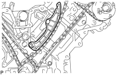
30. REMOVE NO. 1 CHAIN VIBRATION DAMPER LH
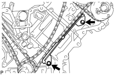
(a) Remove the 2 bolts and chain vibration damper.
31. REMOVE NO. 1 CHAIN SUB-ASSEMBLY LH
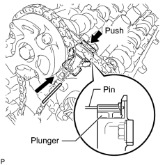
(a) While pushing down the No. 3 chain tensioner, insert a pin of φ1.0 mm (0.0394 in.) into the hole to fix it in place.
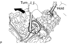
|
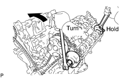
(b) Hold the hexagonal portion of the camshaft with a wrench and loosen the bolt. NOTICE:
|
|
(c) Hold the hexagonal portion of the camshaft with a wrench and loosen the bolt. NOTICE:
Be careful not to damage the cylinder head with the wrench. |
(d) Remove the 2 bolts. Then with the No. 1 and No. 2 chains still connected to the gears, remove the camshaft timing gear, camshaft timing exhaust gear and crankshaft timing sprocket LH.
(e) Remove the No. 1 and No. 2 chains from the gears.
32. REMOVE NO. 3 CHAIN TENSIONER ASSEMBLY
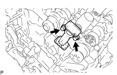
(a) Remove the 2 bolts and chain tensioner.
33. REMOVE NO. 1 CHAIN TENSIONER ASSEMBLY RH
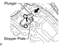
|
(a) Move the stopper plate clockwise to release the lock, and push the plunger deep into the tensioner. |
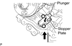
|
(b) Move the stopper plate counterclockwise to set the lock, and insert a hexagon wrench into the stopper plate hole. |
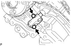
|
(c) Remove the 2 bolts and chain tensioner. |
34. REMOVE NO. 1 CHAIN TENSIONER SLIPPER RH
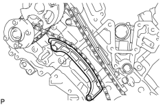
35. REMOVE NO. 1 CHAIN VIBRATION DAMPER RH
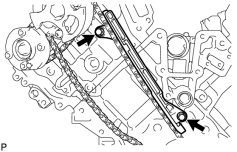
(a) Remove the 2 bolts and vibration damper.
36. REMOVE NO. 1 CHAIN SUB-ASSEMBLY RH
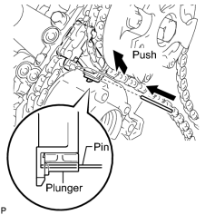
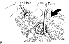
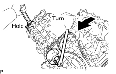
(a) While raising up the No. 2 chain tensioner, insert a pin of φ1.0 mm (0.0394 in.) into the hole to fix it in place.
|
(b) Hold the hexagonal portion of the camshaft with a wrench and loosen the bolt. NOTICE:
|
|
(c) Hold the hexagonal portion of the camshaft with a wrench and loosen the bolt. NOTICE:
Be careful not to damage the cylinder head with the wrench. |
(d) Remove the 2 bolts. Then with the No. 1 and No. 2 chains still connected to the gears, remove the camshaft timing gear, camshaft timing exhaust gear and crankshaft timing sprocket RH.
(e) Remove the No. 1 and No. 2 chains from the gears.
37. REMOVE NO. 2 CHAIN TENSIONER ASSEMBLY
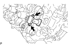
(a) Remove the 2 bolts and chain tensioner.
38. REMOVE CRANKSHAFT TIMING GEAR KEY
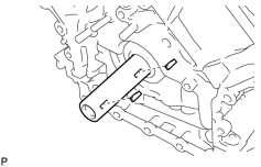
(a) Using a screwdriver, remove the 2 timing gear keys from the crankshaft.
39. REMOVE CAMSHAFT BEARING CAP LH
40. REMOVE CAMSHAFT HOUSING SUB-ASSEMBLY LH
41. REMOVE CAMSHAFT BEARING CAP RH
42. REMOVE CAMSHAFT HOUSING SUB-ASSEMBLY RH
43. REMOVE NO. 1 VALVE ROCKER ARM SUB-ASSEMBLY
(a) Remove the 32 valve rocker arms from the cylinder heads.
HINT:
Arrange the removed parts in the correct order.
44. REMOVE VALVE LASH ADJUSTER ASSEMBLY
(a) Remove the 32 valve lash adjusters from the cylinder heads.
HINT:
Arrange the removed parts in the correct order.
45. REMOVE VALVE STEM CAP
(a) Remove the 32 valve stem caps from the cylinder heads.
HINT:
Arrange the removed parts in the correct order.
46. REMOVE CYLINDER HEAD SUB-ASSEMBLY LH
47. REMOVE CYLINDER HEAD SUB-ASSEMBLY RH
48. REMOVE CYLINDER BLOCK WATER JACKET SPACER
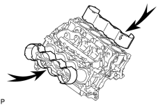
(a) Remove the 2 water jacket spacers from the cylinder block.
NOTICE:
Be sure to remove the water jacket spacers. If not, they may fall and become damaged when the cylinder block is inverted.
49. REMOVE VENTILATION PIPE GASKET
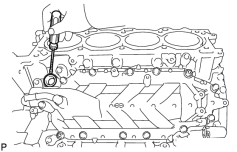
|
(a) Using a screwdriver, pry out the ventilation pipe gasket. HINT:
Tape the screwdriver tip before use. |
50. REMOVE NO. 1 HEAT EXCHANGER COVER
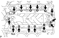
|
(a) Remove the 12 bolts and 2 nuts. |
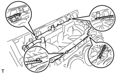
|
(b) Remove the heat exchanger by prying between the heat exchanger and cylinder block with a screwdriver. HINT:
Tape the screwdriver tip before use. |
51. REMOVE NO. 2 OIL PAN SUB-ASSEMBLY
(a) w/ Oil Level Sensor:
Remove the engine oil level sensor
.
|
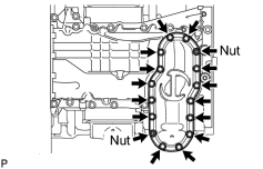
(b) Remove the 14 bolts and 2 nuts. |
|
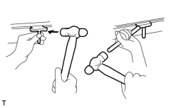
(c) Insert the blade of an oil seal cutter between the oil pans. Cut through the applied sealer and remove the No. 2 oil pan. NOTICE:
Be careful not to damage the contact surfaces of the oil pans. |
52. REMOVE NO. 1 OIL PAN SUB-ASSEMBLY
|
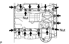
(a) Remove the 14 bolts and 2 nuts. HINT:
Be sure to clean the bolts and stud bolts, and check the threads for cracks or other damage. |
|
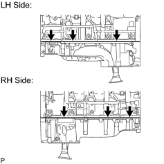
(b) Remove the oil pan by prying between the oil pan and cylinder block with a screwdriver. HINT:
Tape the screwdriver tip before use. NOTICE:
Be careful not to damage the contact surfaces of the cylinder block and oil pan. |
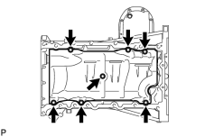
53. REMOVE NO. 1 OIL PAN BAFFLE PLATE
|
(a) Remove the 7 bolts and baffle plate. |
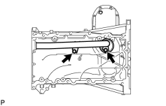
54. REMOVE OIL STRAINER SUB-ASSEMBLY
|
(a) Remove the 2 bolts, oil strainer and O-ring. |
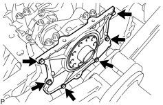
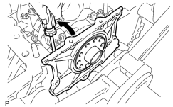
55. REMOVE ENGINE REAR OIL SEAL RETAINER
|
(a) Remove the 6 bolts and oil seal retainer. |
|
(b) Using a screwdriver, pry out the oil seal retainer. HINT:
Tape the screwdriver tip before use. |
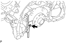
56. REMOVE OIL DRAIN PIPE SUB-ASSEMBLY
|
(a) Remove the bolt and oil drain pipe. |
(b) Remove the O-ring.
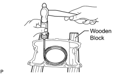
57. REMOVE REAR CRANKSHAFT OIL SEAL
|
(a) Place the oil seal retainer on wooden blocks. |
(b) Using a screwdriver and hammer, tap out the oil seal.
58. REMOVE RING PIN
NOTICE:
It is not necessary to remove the ring pin unless it is being replaced.
59. REMOVE STUD BOLT
NOTICE:
If the stud bolt is deformed or its threads are damaged, replace it.

|

|