| Last Modified: 11-27-2007 | 1.6 A | |
| Service Category: Engine/Hybrid System | Section: Lubrication | |
| Model Year: 2008 | Model: LX570 | Doc ID: RM000002S4X00HX |
| Title: 3UR-FE LUBRICATION: OIL PUMP: REMOVAL (2008 LX570) | ||
REMOVAL
1. REMOVE ENGINE ROOM SIDE COVER LH

2. REMOVE ENGINE ROOM SIDE COVER RH
3. DISCHARGE FUEL SYSTEM PRESSURE
4. DISCONNECT CABLE FROM NEGATIVE BATTERY TERMINAL
NOTICE:
-
w/ Navigation System:
After the engine switch is turned off, the HDD navigation system requires approximately 6 minutes to record various types of memory and settings. As a result, after turning the engine switch off, wait 6 minutes or more before disconnecting the cable from the negative (-) battery terminal.
-
When disconnecting the cable, some systems need to be initialized after the cable is reconnected
.
5. REMOVE UPPER RADIATOR SUPPORT SEAL
6. REMOVE RADIATOR GRILLE
7. DISCONNECT RADIATOR SIDE DEFLECTOR LH
8. DISCONNECT RADIATOR SIDE DEFLECTOR RH (w/o Air Cooled Transmission Oil Cooler)
9. REMOVE COWL TOP VENTILATOR LOUVER SUB-ASSEMBLY
(a) Remove the cowl top ventilator louver
.
10. REMOVE FRONT FENDER APRON SEAL LH
11. REMOVE FRONT FENDER APRON SEAL FRONT RH
12. REMOVE FRONT FENDER SPLASH SHIELD SUB-ASSEMBLY LH
13. REMOVE FRONT FENDER SPLASH SHIELD SUB-ASSEMBLY RH
14. REMOVE NO. 1 ENGINE UNDER COVER SUB-ASSEMBLY
15. REMOVE NO. 2 ENGINE UNDER COVER
16. DRAIN ENGINE OIL
17. DRAIN ENGINE COOLANT
18. REMOVE V-BANK COVER SUB-ASSEMBLY
19. REMOVE AIR CLEANER HOSE ASSEMBLY
20. REMOVE AIR CLEANER ASSEMBLY
21. REMOVE RADIATOR ASSEMBLY
(a) Remove the radiator
.
22. DISCONNECT ENGINE WIRE
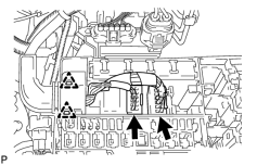
(a) Engine Room LH Side:
|
(1) Remove the engine room relay block cover. |
(2) Disconnect the 2 connectors and 2 clips from the engine room junction block.
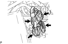
|
(3) Disconnect the 4 air injection control driver connectors and wire harness clamp. |
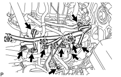
|
(4) Disconnect the injector connector. |
(5) Disconnect the 4 ignition coil connectors.
(6) Disconnect the 2 VVT sensor connectors.
(7) Disconnect the 4 clamps.
(8) Remove the 2 bolts and ground wire.
(9) Disconnect the noise filter connector.
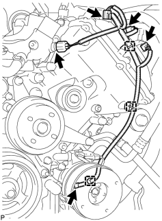
|
(10) Disconnect the engine coolant temperature sensor connector. |
(11) Disconnect the 2 camshaft timing oil control valve connectors.
(12) Disconnect the camshaft position sensor connector.
(13) Disconnect the 3 clamps.
(14) Disconnect the cooler compressor connector.
(b) Engine Room RH Side:
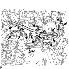
|
(1) Disconnect the 2 camshaft timing oil control valve connectors. |
(2) Disconnect the 4 ignition coil connectors.
(3) Disconnect the injector connector.
(4) Disconnect the 2 VVT sensor connectors.
(5) Disconnect the noise filter connector.
(6) Remove the 2 bolts and ground wire.
(7) Disconnect the 2 air pump connectors.
(8) Disconnect the throttle position sensor and throttle control motor connector.
(9) Disconnect the 5 clamps.
23. DISCONNECT AIR PUMP HOSE AND WIRE HARNESS
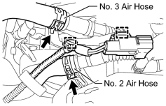
|
(a) Disconnect the No. 2 and No. 3 air hoses. |
(b) Disconnect the 2 clamps.
24. DISCONNECT NO. 2 WATER BY-PASS PIPE
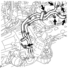
|
(a) Disconnect the 3 hoses. |
(b) Remove the 3 bolts and disconnect the No. 2 water by-pass pipe from the cylinder head cover.
25. DISCONNECT COOLER COMPRESSOR ASSEMBLY
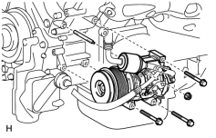
|
(a) Remove the 3 bolts, nut and stud bolt, and disconnect the cooler compressor. HINT:
It is not necessary to completely remove the compressor. With the hoses connected to the compressor, hang the compressor on the vehicle body with a rope. |
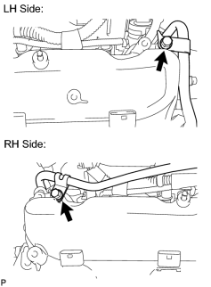
26. DISCONNECT NO. 2 FUEL TUBE SUB-ASSEMBLY
|
(a) Remove the 2 bolts and disconnect the fuel tube. |
27. REMOVE OIL FILTER ELEMENT
28. REMOVE ENGINE OIL LEVEL DIPSTICK GUIDE
29. REMOVE OIL PRESSURE SENDER GAUGE ASSEMBLY
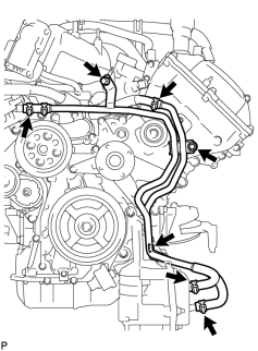
30. REMOVE NO. 2 WATER BY-PASS PIPE SUB-ASSEMBLY (w/ Oil Cooler)
|
(a) Remove the 3 bolts. |
(b) Disconnect the 4 hoses and remove the water by-pass pipe.
31. REMOVE NO. 1 OIL COOLER BRACKET (w/ Oil Cooler)
32. REMOVE OIL FILTER BRACKET (w/ Oil Cooler)
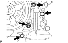
33. REMOVE OIL FILTER BRACKET (w/o Oil Cooler)
|
(a) Remove the 2 bolts, 2 nuts and oil filter bracket. |
|
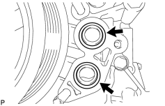
(b) Remove the 2 O-rings. |
34. REMOVE INTAKE MANIFOLD
35. DISCONNECT VANE PUMP ASSEMBLY
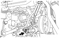
|
(a) Disconnect the 2 clamps and power steering oil pressure switch connector. |
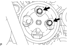
|
(b) Remove the 2 bolts and disconnect the vane pump. |
36. DISCONNECT OIL COOLER PIPE ASSEMBLY
37. REMOVE GENERATOR ASSEMBLY
38. REMOVE NO. 1 WATER BY-PASS HOSE
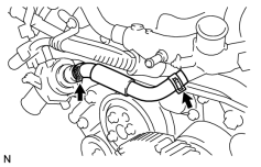
|
(a) Remove the No. 1 water by-pass hose by disconnecting the hose from the water inlet housing and front water by-pass joint. |
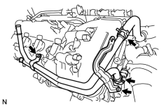
39. REMOVE WATER BY-PASS PIPE SUB-ASSEMBLY
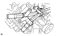
|
(a) Remove the bolt and disconnect the air tube. |
(b) Disconnect the 2 hoses.
|
(c) Remove the 2 bolts and water by-pass pipe. |
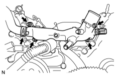
40. REMOVE FRONT WATER BY-PASS JOINT
|
(a) Disconnect the No. 2 water by-pass hose from the water by-pass joint. |
(b) Remove the 4 nuts, water by-pass joint and 2 gaskets.
41. REMOVE NO. 2 ENGINE COVER
42. REMOVE NO. 1 ENGINE COVER
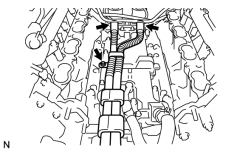
43. REMOVE AIR TUBE SUB-ASSEMBLY
|
(a) Remove the bolt, disconnect the 2 hoses, and remove the air tube. |
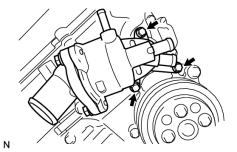
44. REMOVE WATER INLET HOUSING
|
(a) Remove the 3 bolts, water inlet housing and gasket. |
45. REMOVE WATER PUMP PULLEY
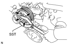
|
(a) Using SST, hold the water pump pulley. SST: 09960-10010 09962-01000 09963-01000 |
(b) Remove the 4 bolts and water pump pulley.
46. REMOVE NO. 1 IDLER PULLEY SUB-ASSEMBLY
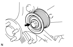
|
(a) Remove the bolt and idler pulley. |
47. REMOVE FLUID COUPLING BRACKET
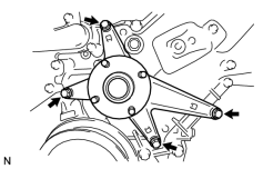
|
(a) Remove the 4 bolts and fluid coupling bracket. |
48. REMOVE V-RIBBED BELT TENSIONER ASSEMBLY
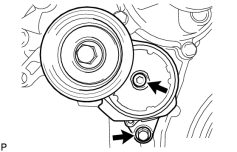
|
(a) Remove the standard bolt, 6 mm hexagon wrench bolt and belt tensioner. |
49. REMOVE IGNITION COIL ASSEMBLY
(a) Remove the 8 bolts and 8 ignition coils.
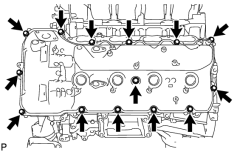
50. REMOVE CYLINDER HEAD COVER SUB-ASSEMBLY LH
|
(a) Remove the 14 bolts, seal washer, cylinder head cover and gasket. HINT:
Make sure the removed parts are returned to the same places they were removed from. |
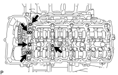
|
(b) Remove the 5 gaskets from the camshaft bearing caps (No. 2, No. 3). |
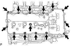
51. REMOVE CYLINDER HEAD COVER SUB-ASSEMBLY RH
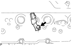
|
(a) Remove the bolt and noise filter. |
|
(b) Remove the 14 bolts, seal washer, cylinder head cover and gasket. HINT:
Make sure the removed parts are returned to the same places they were removed from. |
|
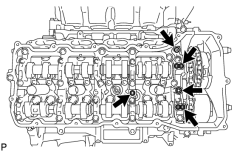
(c) Remove the 5 gaskets from the camshaft bearing caps (No. 1, No. 3). |
52. REMOVE SPARK PLUG TUBE GASKET
53. REMOVE CRANKSHAFT PULLEY
|
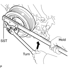
(a) Using SST, loosen the crankshaft pulley set bolt until 2 or 3 threads are engaged. SST: 09213-70011 09213-70020 SST: 09330-00021 |
|
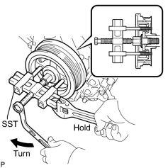
(b) Using the pulley set bolt and SST, remove the crankshaft pulley. SST: 09950-50013 09951-05010 09952-05010 09953-05010 09954-05011 |
54. DISCONNECT WIRE HARNESS CLAMP BRACKET
|
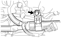
(a) Remove the bolt and disconnect the bracket. |
55. REMOVE CRANKSHAFT TIMING GEAR KEY
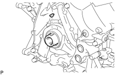
|
(a) Using a screwdriver, remove the timing gear key from the crankshaft. |
56. REMOVE TIMING CHAIN COVER SUB-ASSEMBLY
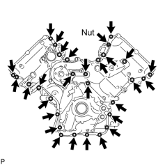
|
(a) Remove the 28 bolts and nut shown in the illustration. |
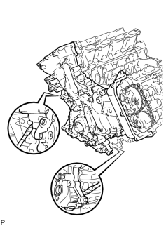
|
(b) Remove the timing chain cover by prying between the timing chain cover and cylinder head or cylinder block with a screwdriver as shown in the illustration. NOTICE:
Be careful not to damage the contact surfaces of the cylinder head, cylinder block and chain cover. HINT:
Tape the screwdriver tip before use. |
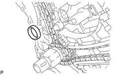
|
(c) Remove the oil pump gasket from the cylinder block. |
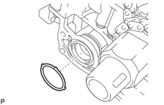
|
(d) Remove the O-ring from the oil pan. |
57. REMOVE WATER INLET PIPE
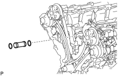
|
(a) Remove the water inlet pipe. |
(b) Remove the 2 O-rings from the water inlet pipe.

|

|