Timing Chain Cover Removal and Installation
Precautions: General safety (00)
Removal
1)Remove engine assembly from vehicle. 
2)Remove water pump / generator drive belt.
3)Remove crankshaft pulley bolt (1).
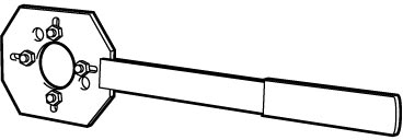
To lock crankshaft pulley (2), use special tool as shown in figure.


To lock crankshaft pulley (2), use special tool as shown in figure.
4)Remove crankshaft pulley (1).
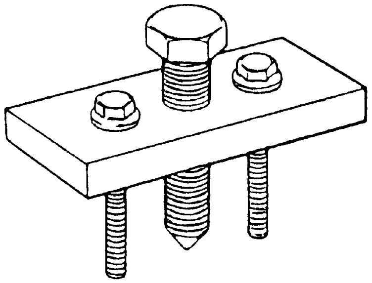
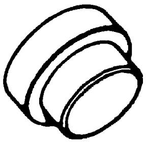
If it cannot be removed by hand, use special tools as shown in figure.
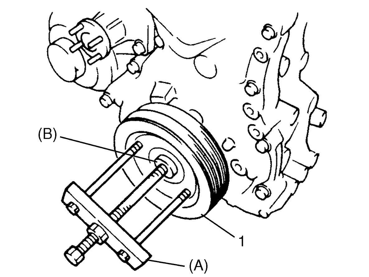
If it cannot be removed by hand, use special tools as shown in figure.
5)Remove cylinder head cover.
6)Remove oil pan.
7)Remove water pump pulley.
8)For A/C model, remove compressor bracket from cylinder block and timing chain cover.
9)Remove oil gallery pipes No.2 (1) and No.3 (2).
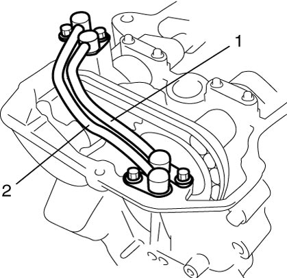
10)Remove timing chain cover.
11)Remove OCV from timing chain cover.
12)Remove oil pump from timing chain cover.
Installation
1)Clean sealing surface of timing chain cover, cylinder block and cylinder head.
Remove oil, old sealant and dust from sealing surface.
Remove oil, old sealant and dust from sealing surface.
2)Install oil pump to timing chain cover.
3)Check oil seal (1) lip for fault or other damage.
Replace oil seal, if necessary.
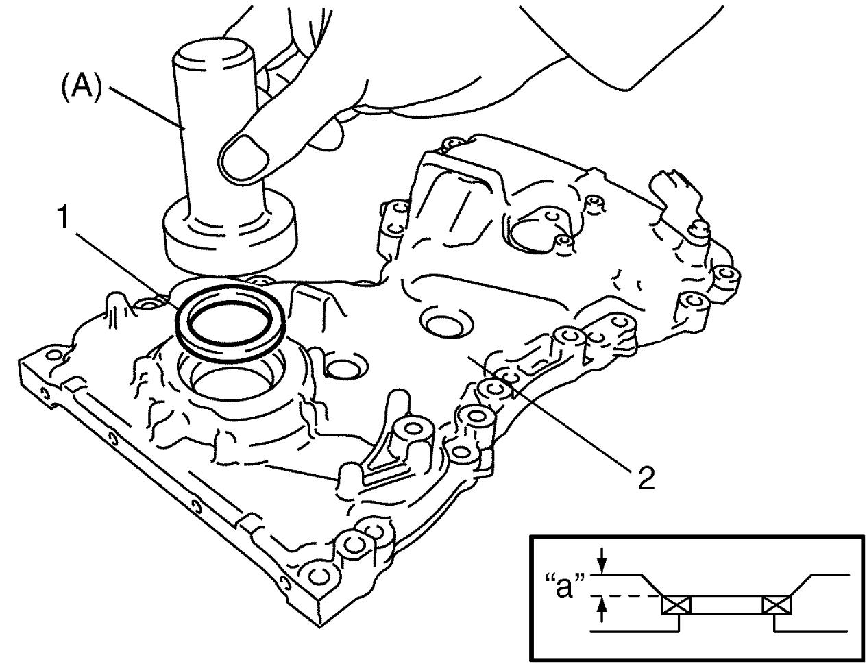
Replace oil seal, if necessary.
NOTE:
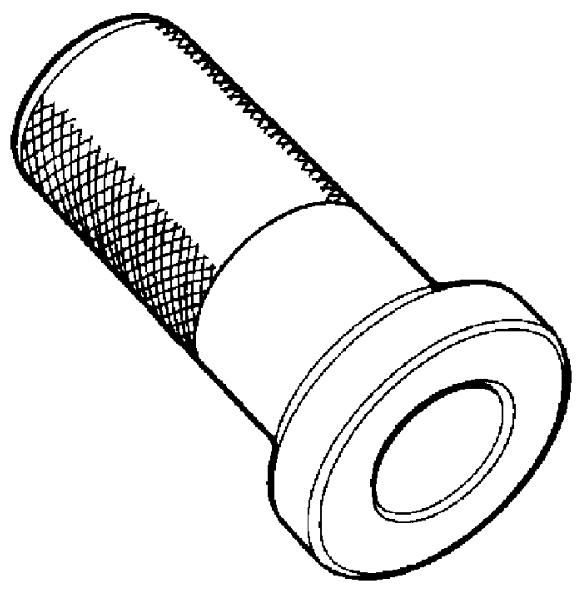
When installing new oil seal, press-fit to timing chain cover (2) using special tool as shown in figure.
Depth
“a”: 0.1 – 1.6 mm (0.004 – 0.063 in.)
4)Install OCV and new OCV gasket to timing chain cover.
5)Apply sealant “A” to mating surface of timing chain cover as shown in figure.
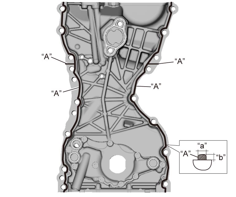
Sealant amount for timing chain cover
Width “a”: 3 mm (0.12 in.)
Height “b”: 2 mm (0.08 in.)
6)Apply engine oil to new O-rings (1) and then install O-rings to rotor plate (2).
7)Check that dowel pins (3) are installed to timing chain cover (4).
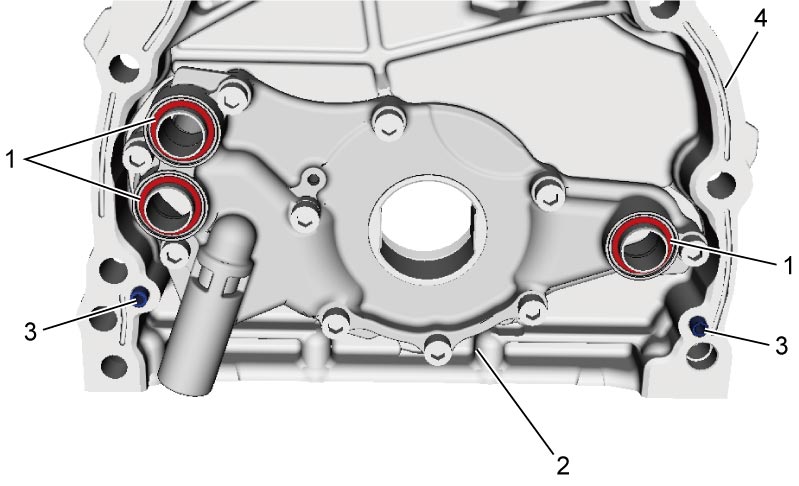
8)Apply engine oil to oil seal lip and then install timing chain cover.
9)Tighten timing chain cover bolts and nut in numerical order (“1” – “18”) evenly and gradually to specified torque.
Timing chain cover nut* (b): 25 N·m (2.5 kgf-m, 18.5 lbf-ft)
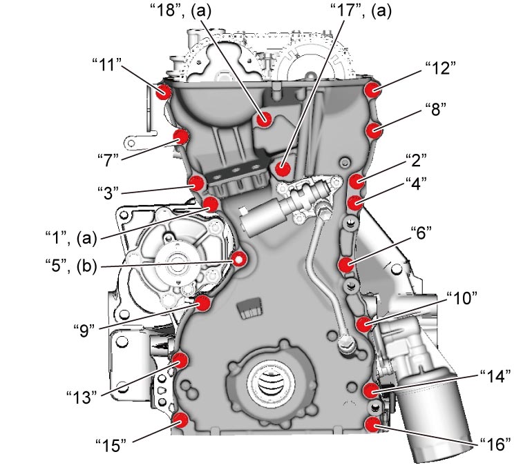
Tightening torque
Timing chain cover bolt* (a): 25 N·m (2.5 kgf-m, 18.5 lbf-ft)Timing chain cover nut* (b): 25 N·m (2.5 kgf-m, 18.5 lbf-ft)
10)Apply engine oil to new O-ring (1) and then install O-ring to oil gallery pipes No.2 (2) and No.3 (3).
11)Install oil gallery pipes No.2 and No.3 to cylinder head (4) and timing chain cover (5).
Tighten oil gallery pipe No.2 bolts and oil gallery pipe No.3 bolts to specified torque.
Oil gallery pipe No.3 bolt (b): 11 N·m (1.1 kgf-m, 8.5 lbf-ft)
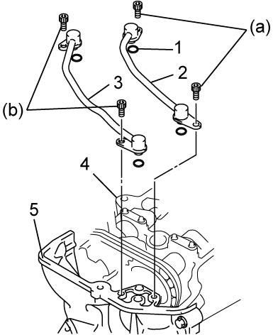
Tighten oil gallery pipe No.2 bolts and oil gallery pipe No.3 bolts to specified torque.
Tightening torque
Oil gallery pipe No.2 bolt (a): 11 N·m (1.1 kgf-m, 8.5 lbf-ft)Oil gallery pipe No.3 bolt (b): 11 N·m (1.1 kgf-m, 8.5 lbf-ft)
12)For A/C model, install compressor bracket.
•Manual A/C model:
•Auto A/C model:
•Auto A/C model:
13)Install water pump pulley.
14)Install cylinder head cover.
15)Install oil pan.
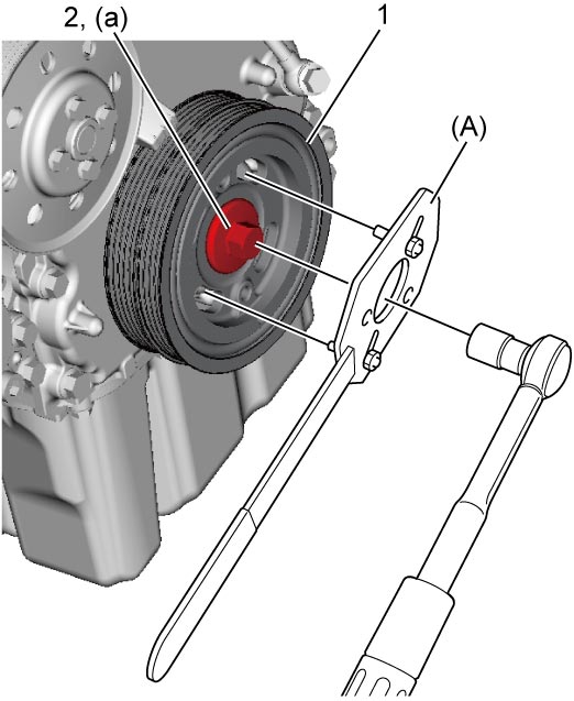
16)Install crankshaft pulley (1). Tighten crankshaft pulley bolt (2) to specified torque. To lock crankshaft pulley, use special tool as shown in figure.
17)Install water pump / generator drive belt.
18)Install engine assembly to vehicle.