DTC C104C
Precautions: Precautions for ESP® · Precautions for Diagnosing Trouble · Test with Speedometer Tester or Other Equipment · Precautions for Brakes · General safety (00)
DTC Detecting Condition and Trouble Area
| DTC detecting condition | Trouble area |
|---|---|
|
C104C: Neutral Position Switch System Malfunction Neutral position switch signal is out of specified range. |
•Neutral position switch
•Neutral position switch circuit •ESP® control module |
Circuit Diagram
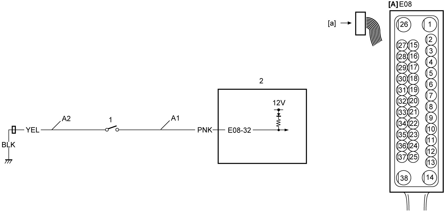
| [A]: | ESP® control module connector (View: [a]) | A2: | Neutral position switch ground circuit | 2. | ESP® control module |
| A1: | Neutral position switch signal circuit | 1. | Neutral position switch |
DTC Troubleshooting
| Step | Action | Yes | No |
|---|---|---|---|
| 1 |
Was “ESP® System Check” performed?
|
Go to Step 2.
|
Go to ESP® System Check.
|
| 2 |
Neutral position switch signal circuit check
1)With ignition “OFF”, disconnect neutral position switch connector.
2)Check for proper connection to neutral position switch connector.
3)If connections are OK, set ignition “ON”.
4)Check that voltage between “A1” circuit and ground is approx. 12 V.
Is check result OK?
|
Go to Step 3.
|
Repair or replace defective wire harness.
|
| 3 |
Neutral position switch ground circuit check
1)Set ignition “OFF”.
2)Check that resistance between “A2” circuit and ground is less than 1 Ω.
Is check result OK?
|
Go to Step 4.
|
Repair or replace defective wire harness.
|
| 4 |
Neutral position switch check
1)Check neutral position switch.
•M16A model:
 •K14C model: •D16AA model: Is check result OK?
|
Replace ESP® hydraulic unit / control module assembly and recheck DTC.
|
Replace neutral position switch.
•M16A model:
•K14C model: •D16AA model: |