RBS Control Module Removal and Installation
Precautions: Precautions for Diagnosing Trouble · Precautions for RBS System · Precautions for Servicing RBS System · Precautions for Removing / Installing and Replacing RBS Control Module · Precautions for Control Systems · General safety (00)
NOTICE:
Removal of RBS control module may weaken clips’ retaining force and cause looseness or dropping off of RBS control module after reinstallation.
Replace the clips with new ones when reinstalling RBS control module.
Removal
1)Disconnect negative (–) cable at battery.
2)Remove front bumper. 
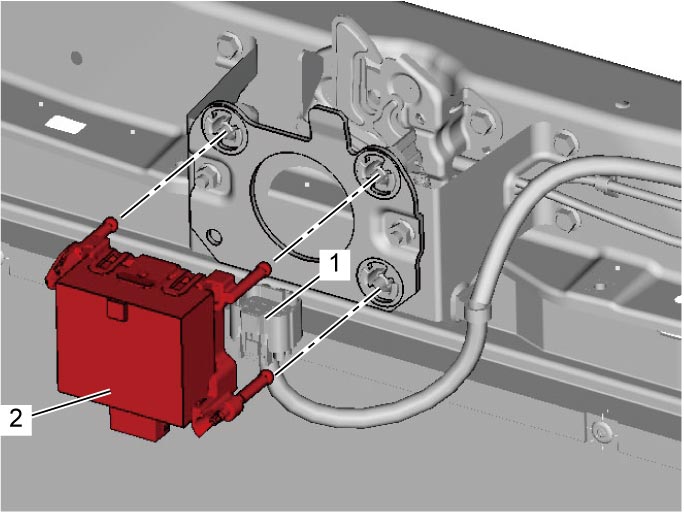
3)Disconnect connector (1) and remove RBS control module (2).

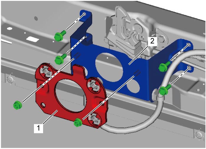
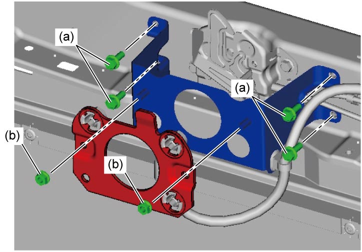
4)Remove RBS control module No.1 bracket (1) and No.2 bracket (2).
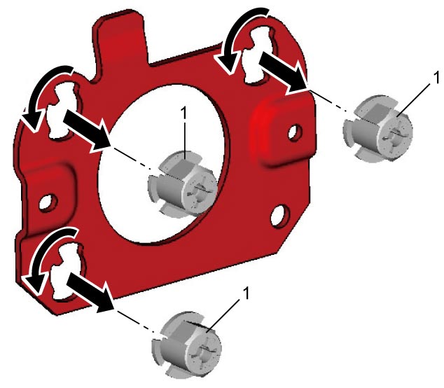
5)Remove clips (1).
Installation
Reverse removal procedure noting the following points.
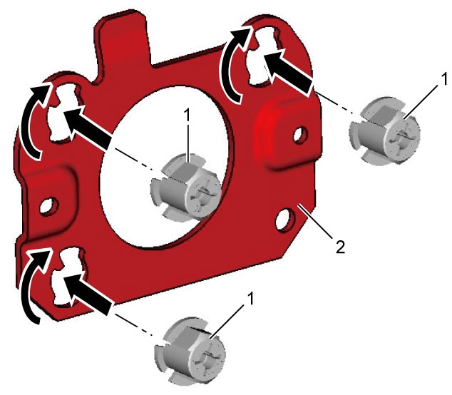
•Use new clips (1).
•Insert new clip to RBS control module No.1 bracket (2) at each hole and turn it clockwise until it stops.
 •Tighten RBS control module bracket bolts and nuts to specified torque.
RBS control module bracket nut (b): 12 N·m (1.2 kgf-m, 9.0 lbf-ft)
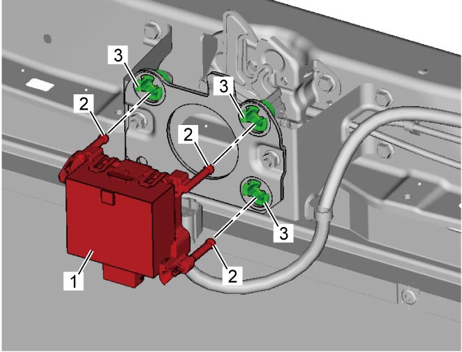
 •Install RBS control module (1) inserting aiming bolts (2) to clips (3) until tightness is felt.
 •After installation, perform Millimeter Wave Radar Aiming Adjustment.
•Insert new clip to RBS control module No.1 bracket (2) at each hole and turn it clockwise until it stops.
Tightening torque
RBS control module bracket bolt (a): 10 N·m (1.0 kgf-m, 7.5 lbf-ft)RBS control module bracket nut (b): 12 N·m (1.2 kgf-m, 9.0 lbf-ft)