Home › Engine / Hybrid System › 1GR-FE ENGINE CONTROL › SFI SYSTEM › from 2014.08
RM1440E _51 Engine / Hybrid System _056124 1GR-FE ENGINE CONTROL _0273876 SFI SYSTEM J

1GR-FE ENGINE CONTROL  SFI SYSTEM  Fuel Pump Control Circuit  


DESCRIPTION

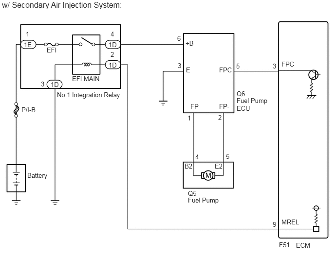
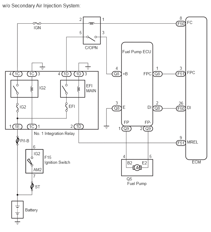
The fuel pump circuit consists of the ECM, fuel pump and fuel pump ECU (which operates the fuel pump). Based on the engine output, the ECM determines the fuel pump speed. The speed is then converted to a duty signal and sent to the fuel pump ECU. Based on the signal sent from the ECM, the fuel pump ECU adjusts the fuel pump operation speed.

WIRING DIAGRAM
A327948E02
1.146,0.854 1.438,1.01 0.292,0.156 10 false IGN 0.083,0.083 2.802,0.448 2.719,0.365 12 false w/o Secondary Air Injection System: 0.313,2.417 0.438,2.573 0.125,0.156 10 false 4 0.5,2.417 0.708,2.583 0.208,0.167 10 false 1C 0.313,4.198 0.438,4.354 0.125,0.156 10 false 1 1.281,2.417 1.406,2.573 0.125,0.156 10 false 3 1.281,4.198 1.406,4.354 0.125,0.156 10 false 1 0.5,4.208 0.708,4.375 0.208,0.167 10 false 1E 0.99,2.417 1.198,2.583 0.208,0.167 10 false 1C 0.99,4.208 1.198,4.375 0.208,0.167 10 false 1C 2.396,4.198 2.521,4.354 0.125,0.156 10 false 2 2.583,4.198 2.792,4.365 0.208,0.167 10 false 1D 2.583,2.417 2.792,2.583 0.208,0.167 10 false 1D 1.969,2.417 2.094,2.573 0.125,0.156 10 false 4 2.875,2.417 3,2.573 0.125,0.156 10 false 3 2.156,2.417 2.365,2.583 0.208,0.167 10 false 1D 1.156,4.438 2.615,4.615 1.458,0.177 10 false No. 1 Integration Relay 1.333,2.896 1.594,3.042 0.26,0.146 10 false IG2 0.667,3.542 0.927,3.688 0.26,0.146 10 false IG2 2.333,3.521 2.594,3.677 0.26,0.156 10 false EFI 2.927,2.823 3.302,3.146 0.375,0.323 10 false EFI MAIN 0.688,4.688 1.021,4.833 0.333,0.146 10 false P/I-B 1.188,6.25 1.396,6.406 0.208,0.156 10 false ST 0.854,7.031 1.333,7.219 0.479,0.188 10 false Battery 1.51,5.25 1.802,5.406 0.292,0.156 10 false F15 1.51,5.417 2.521,5.656 1.01,0.24 10 false Ignition Switch 1.146,5.125 1.406,5.281 0.26,0.156 10 false IG2 1.135,5.667 1.448,5.823 0.313,0.156 10 false AM2 1.125,4.896 1.24,5.063 0.115,0.167 10 false 6 1.125,5.885 1.24,6.052 0.115,0.167 10 false 7 2.698,0.573 2.802,0.729 0.104,0.156 10 false 2 3.469,0.573 3.573,0.729 0.104,0.156 10 false 1 2.698,1.021 2.802,1.177 0.104,0.156 10 false 5 3.469,1.021 3.573,1.177 0.104,0.156 10 false 3 2.885,1.531 3.365,1.698 0.479,0.167 10 false C/OPN 4.156,1.667 5.198,1.813 1.042,0.146 10 false Fuel Pump ECU 3.927,2.229 4.042,2.385 0.115,0.156 10 false 4 3.865,2.417 4.094,2.563 0.229,0.146 10 false Q8 3.927,3.406 4.042,3.563 0.115,0.156 10 false 3 4.021,4.271 4.135,4.427 0.115,0.156 10 false 1 3.875,3.583 4.104,3.729 0.229,0.146 10 false Q8 4.198,4.271 4.427,4.417 0.229,0.146 10 false Q9 4.76,4.271 4.875,4.427 0.115,0.156 10 false 2 4.938,4.271 5.167,4.417 0.229,0.146 10 false Q9 5.302,2.229 5.417,2.385 0.115,0.156 10 false 1 5.25,2.417 5.479,2.563 0.229,0.146 10 false Q8 5.302,3.406 5.417,3.563 0.115,0.156 10 false 2 5.25,3.583 5.479,3.729 0.229,0.146 10 false Q8 4.177,5.219 4.292,5.365 0.115,0.146 10 false 4 5.073,5.219 5.188,5.365 0.115,0.146 10 false 5 4.323,5.438 4.542,5.594 0.219,0.156 10 false B2 4.823,5.438 5.042,5.594 0.219,0.156 10 false E2 4.302,5.979 4.531,6.125 0.229,0.146 10 false Q5 4.323,6.135 5.031,6.323 0.708,0.188 10 false Fuel Pump 6.104,0.531 6.229,0.677 0.125,0.146 10 false 8 6.031,0.719 6.313,0.865 0.281,0.146 10 false F50 6.354,0.677 6.583,0.833 0.229,0.156 10 false FC 6.104,2.229 6.229,2.375 0.125,0.146 10 false 3 6.031,2.417 6.313,2.563 0.281,0.146 10 false F51 6.354,2.375 6.667,2.531 0.313,0.156 10 false FPC 6.073,3.417 6.26,3.563 0.188,0.146 10 false 26 6.031,3.594 6.313,3.74 0.281,0.146 10 false F50 6.354,3.563 6.583,3.719 0.229,0.156 10 false DI 6.104,4.583 6.229,4.729 0.125,0.146 10 false 9 6.031,4.76 6.313,4.906 0.281,0.146 10 false F51 6.354,4.729 6.781,4.885 0.427,0.156 10 false MREL 6.521,5.406 6.875,5.573 0.354,0.167 10 false ECM 4.167,2.417 4.396,2.573 0.229,0.156 10 false +B 4.875,2.417 5.177,2.573 0.302,0.156 10 false FPC 4.167,3.552 4.302,3.708 0.135,0.156 10 false E 5.01,3.552 5.188,3.708 0.177,0.156 10 false DI 4.208,4.063 4.438,4.219 0.229,0.156 10 false FP 4.917,4.063 5.177,4.219 0.26,0.156 10 false FP-

A288680E05
0.583,3.677 1.073,3.865 0.49,0.188 10 false Battery 0.458,2.271 0.823,2.438 0.365,0.167 10 false P/I-B 0.552,0.646 0.677,0.813 0.125,0.167 10 false 1 0.51,0.875 0.74,1.042 0.229,0.167 10 false 1E 2.365,0.646 2.49,0.813 0.125,0.167 10 false 4 0.875,1.719 1,1.885 0.125,0.167 10 false 3 2.323,0.875 2.552,1.042 0.229,0.167 10 false 1D 2.365,1.083 2.49,1.25 0.125,0.167 10 false 2 2.323,1.313 2.552,1.479 0.229,0.167 10 false 1D 1.083,1.729 1.313,1.896 0.229,0.167 10 false 1D 1,0.99 1.271,1.156 0.271,0.167 10 false EFI 1.542,1.604 2.188,1.771 0.646,0.167 10 false EFI MAIN 1.219,1.948 2.698,2.177 1.479,0.229 10 false No.1 Integration Relay 0.042,0 2.771,0.406 2.729,0.406 12 false w/ Secondary Air Injection System: 3.792,0.74 3.906,0.906 0.115,0.167 10 false 6 3.802,1.323 3.917,1.49 0.115,0.167 10 false 3 5.052,1.333 5.167,1.5 0.115,0.167 10 false 5 3.969,0.844 4.198,1.01 0.229,0.167 10 false +B 3.979,1.417 4.167,1.594 0.188,0.177 10 false E 4.073,2.198 4.313,2.375 0.24,0.177 10 false FP 4.688,2.198 4.958,2.375 0.271,0.177 10 false FP- 4.688,1.417 5.031,1.583 0.344,0.167 10 false FPC 4.667,2.438 4.781,2.604 0.115,0.167 10 false 2 4.01,2.448 4.125,2.615 0.115,0.167 10 false 1 5.063,1.927 5.354,2.094 0.292,0.167 10 false Q6 5.063,2.073 5.885,2.427 0.823,0.354 10 false Fuel Pump ECU 4.021,4.063 4.313,4.229 0.292,0.167 10 false Q5 4.021,4.208 4.917,4.563 0.896,0.354 10 false Fuel Pump 6.333,5.177 6.688,5.365 0.354,0.188 10 false ECM 6.021,1.292 6.427,1.458 0.406,0.167 10 false FPC 6.021,4.677 6.427,4.844 0.406,0.167 10 false MREL 4.833,3.271 4.948,3.438 0.115,0.167 10 false 5 4.177,3.281 4.292,3.448 0.115,0.167 10 false 4 5.969,5.167 6.26,5.333 0.292,0.167 10 false F51 5.833,1.333 5.948,1.5 0.115,0.167 10 false 3 5.833,4.729 5.948,4.896 0.115,0.167 10 false 9 3.948,3.479 4.167,3.646 0.219,0.167 10 false B2 4.594,3.479 4.813,3.646 0.219,0.167 10 false E2

CAUTION / NOTICE / HINT

NOTICE:

Inspect the fuses for circuits related to this system before performing the following inspection procedure.


This troubleshooting procedure is based on the premise that the engine can be started. If the engine cannot be started, proceed to Problem Symptoms Table (See page Engine / Hybrid System>1GR-FE ENGINE CONTROL>SFI SYSTEM>PROBLEM SYMPTOMS TABLE).

PROCEDURE

1.PERFORM ACTIVE TEST USING GTS (CONTROL THE FUEL PUMP/SPEED)
a.

Connect the GTS to the DLC3.


b.

Turn the ignition switch to ON.


c.

Turn the GTS on.


d.

Enter the following menus: Powertrain / Engine and ECT / Active Test / Control the Fuel Pump/Speed.


e.

Check whether operating sounds can be heard while operating the fuel pump using the GTS.

OK:

Operating sounds can be heard from fuel pump.


Result
Result Proceed to
NG (w/o Secondary Air Injection System) A
OK (w/ Secondary Air Injection System) B
NG (w/ Secondary Air Injection System) C
OK (w/o Secondary Air Injection System) D


A

2.INSPECT CIRCUIT OPENING RELAY (C/OPN)

B

11.PERFORM ACTIVE TEST USING GTS (CONTROL THE FUEL PUMP)

C

16.INSPECT FUEL PUMP ECU (POWER SOURCE VOLTAGE)

D

PROCEED TO NEXT SUSPECTED AREA SHOWN IN PROBLEM SYMPTOMS TABLE

2.INSPECT CIRCUIT OPENING RELAY (C/OPN)
a.

Inspect the circuit opening relay (C/OPN) (See page Engine / Hybrid System>1GR-FE ENGINE CONTROL>RELAY>ON-VEHICLE INSPECTION).


OK

3.INSPECT CIRCUIT OPENING RELAY (C/OPN) (POWER SOURCE VOLTAGE)

NG

REPLACE CIRCUIT OPENING RELAY (C/OPN)

3.INSPECT CIRCUIT OPENING RELAY (C/OPN) (POWER SOURCE VOLTAGE)
A227634E01
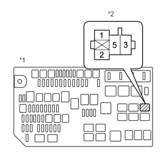
0.405,1.177 0.608,1.333 0.202,0.156 10 *1 2.262,0.209 2.464,0.365 0.202,0.156 10 *2

a.

Remove the circuit opening relay (C/OPN) from the engine room relay block.


b.

Turn the ignition switch to ON.


c.

Measure the voltage according to the value(s) in the table below.

Standard Voltage:
Tester Connection Switch Condition Specified Condition
Circuit opening relay (C/OPN) terminal 2 - Body ground Ignition switch ON 11 to 14 V
Circuit opening relay (C/OPN) terminal 5 - Body ground Ignition switch ON 11 to 14 V


Text in Illustration
*1 Engine Room Relay Block
*2 Circuit Opening Relay (C/OPN)


OK

4.CHECK HARNESS AND CONNECTOR (CIRCUIT OPENING RELAY (C/OPN) - ECM AND FUEL PUMP ECU)

NG

10.CHECK HARNESS AND CONNECTOR (CIRCUIT OPENING RELAY (C/OPN) - NO. 1 INTEGRATION RELAY)
4.CHECK HARNESS AND CONNECTOR (CIRCUIT OPENING RELAY (C/OPN) - ECM AND FUEL PUMP ECU)
a.

Remove the circuit opening relay (C/OPN) from the engine room relay block.


b.

Disconnect the ECM connector.


c.

Disconnect the fuel pump ECU connector.


d.

Measure the resistance according to the value(s) in the table below.

Standard Resistance:
Tester Connection Condition Specified Condition
Circuit opening relay (C/OPN) terminal 1 - F50-8 (FC) Always Below 1 Ω
Circuit opening relay (C/OPN) terminal 3 - Q8-4 (+B) Always Below 1 Ω
Circuit opening relay (C/OPN) terminal 1 or F50-8 (FC) - Body ground Always 10 kΩ or higher
Circuit opening relay (C/OPN) terminal 3 or Q8-4 (+B) - Body ground Always 10 kΩ or higher


OK

5.CHECK HARNESS AND CONNECTOR (FUEL PUMP - FUEL PUMP ECU)

NG

REPAIR OR REPLACE HARNESS OR CONNECTOR

5.CHECK HARNESS AND CONNECTOR (FUEL PUMP - FUEL PUMP ECU)
a.

Disconnect the fuel pump connector.


b.

Disconnect the fuel pump ECU connector.


c.

Measure the resistance according to the value(s) in the table below.

Standard Resistance:
Tester Connection Condition Specified Condition
Q5-4 (B2) - Q9-1 (FP) Always Below 1 Ω
Q5-5 (E2) - Q9-2 (FP-) Always Below 1 Ω
Q5-4 (B2) or Q9-1 (FP) - Body ground Always 10 kΩ or higher
Q5-5 (E2) or Q9-2 (FP-) - Body ground Always 10 kΩ or higher


OK

6.INSPECT FUEL PUMP

NG

REPAIR OR REPLACE HARNESS OR CONNECTOR

6.INSPECT FUEL PUMP
a.


OK

7.CHECK HARNESS AND CONNECTOR (FUEL PUMP ECU - ECM AND BODY GROUND)

NG

7.CHECK HARNESS AND CONNECTOR (FUEL PUMP ECU - ECM AND BODY GROUND)
a.

Disconnect the fuel pump ECU connector.


b.

Disconnect the ECM connectors.


c.

Measure the resistance according to the value(s) in the table below.

Standard Resistance:
Tester Connection Condition Specified Condition
Q8-1 (FPC) - F51-3 (FPC) Always Below 1 Ω
Q8-2 (DI) - F50-26 (DI) Always Below 1 Ω
Q8-3 (E) - Body ground Always Below 1 Ω
Q8-1 (FPC) or F51-3 (FPC) - Body ground Always 10 kΩ or higher
Q8-2 (DI) or F50-26 (DI) - Body ground Always 10 kΩ or higher


OK

8.REPLACE FUEL PUMP ECU

NG

REPAIR OR REPLACE HARNESS OR CONNECTOR

8.REPLACE FUEL PUMP ECU
a.

Replace the fuel pump ECU (see page Engine / Hybrid System>1GR-FE FUEL>FUEL PUMP ECU>REMOVAL).


NEXT

9.CONFIRM WHETHER MALFUNCTION HAS BEEN SUCCESSFULLY REPAIRED
a.

Check the fuel pump operation.

OK:

Malfunction has been repaired successfully.


OK

END

NG

10.CHECK HARNESS AND CONNECTOR (CIRCUIT OPENING RELAY (C/OPN) - NO. 1 INTEGRATION RELAY)
a.

Remove the circuit opening relay (C/OPN) from the engine room relay block.


b.

Remove the No. 1 integration relay from the engine room relay block.


c.

Measure the resistance according to the value(s) in the table below.

Standard Resistance:
Tester Connection Condition Specified Condition
Circuit opening relay (C/OPN) terminal 2 - 1C-4 Always Below 1 Ω
Circuit opening relay (C/OPN) terminal 5 - 1D-4 Always Below 1 Ω
Circuit opening relay (C/OPN) terminal 2 or 1C-4 - Body ground Always 10 kΩ or higher
Circuit opening relay (C/OPN) terminal 5 or 1D-4 - Body ground Always 10 kΩ or higher


OK

NG
REPAIR OR REPLACE HARNESS OR CONNECTOR

11.PERFORM ACTIVE TEST USING GTS (CONTROL THE FUEL PUMP)
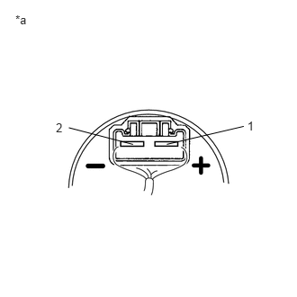
A243665E02
2.862,1.37 2.973,1.519 0.111,0.149 10 1 0.647,1.391 0.755,1.544 0.107,0.152 10 2 1.931,1.67 2.821,1.462 false 1.539,1.671 0.796,1.478 false 0.178,0.144 2.543,0.541 2.365,0.397 10 *a

a.

Remove the fuel tank assembly (See page Engine / Hybrid System>1GR-FE FUEL>FUEL TANK>REMOVAL).


b.

Remove the fuel pump from the fuel tank assembly.


c.

Clean the fuel pump to completely remove any remaining fuel.


d.

Connect the fuel pump connector.

CAUTION:

Make sure that there is no fuel remaining inside or on the outside of the fuel pump.


e.

Connect the GTS to the DLC3.


f.

Turn the ignition switch to ON.


g.

Turn the GTS on.


h.

Enter the following menus: Powertrain / Engine and ECT / Active Test / Control the Fuel Pump Duty.


i.

Operate the fuel pump using the Active Test function and measure the voltage according to the value(s) in the table below.

Standard Voltage:
Tester Connection GTS Operation Specified Condition
1 - 2 FPC Duty: 25% 3.2 to 4.05 V
FPC Duty: 80% 8.8 to 12.5 V


j.

Enter the following menus: Powertrain / Engine and ECT / Active Test / Control the Fuel Pump/Speed.


k.

Operate the fuel pump using the Active Test function and measure the voltage according to the value(s) in the table below.

Standard Voltage:
Tester Connection GTS Operation Specified Condition
1 - 2 ON (FPC Duty: 90%) 9.0 to 14.0 V


HINT:
·

Be sure to measure the voltage with all the connectors connected.

·

Before performing this inspection, check that the battery voltage is between 11 and 14 V (not depleted).


Text in Illustration
*a Component with harness connected
(Fuel Pump)


OK

12.CHECK HARNESS AND CONNECTOR (FUEL PUMP ECU - ECM)

NG

14.REPLACE FUEL PUMP ECU
12.CHECK HARNESS AND CONNECTOR (FUEL PUMP ECU - ECM)
a.

Disconnect the fuel pump ECU connector.


b.

Disconnect the ECM connector.


c.

Measure the resistance according to the value(s) in the table below.

Standard Resistance:
Tester Connection Condition Specified Condition
Q6-5 (FPC) - F51-3 (FPC) Always Below 1 Ω
Q6-5 (FPC) or F51-3 (FPC) - Body ground Always 10 kΩ or higher


OK

13.REPLACE FUEL PUMP

NG

REPAIR OR REPLACE HARNESS OR CONNECTOR

13.REPLACE FUEL PUMP
a.

Replace the fuel pump (See page Engine / Hybrid System>1GR-FE FUEL>FUEL PUMP>REMOVAL).


NEXT

15.CONFIRM WHETHER MALFUNCTION HAS BEEN SUCCESSFULLY REPAIRED
14.REPLACE FUEL PUMP ECU
a.

Replace the fuel pump ECU (See page Engine / Hybrid System>1GR-FE FUEL>FUEL PUMP ECU>REMOVAL).


NEXT

15.CONFIRM WHETHER MALFUNCTION HAS BEEN SUCCESSFULLY REPAIRED
a.

Check the fuel pump operation.

OK:

Malfunction has been repaired successfully.


OK

END

NG

16.INSPECT FUEL PUMP ECU (POWER SOURCE VOLTAGE)
U149652E01
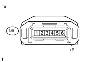
2.436,1.675 2.630,1.827 0.194,0.152 10 +B 2.244,1.204 2.538,1.66 false 0.31,0.985 0.560,1.127 0.250,0.142 10 Q6 0.08,0.134 0.398,0.388 0.318,0.253 10 *a

a.

Disconnect the fuel pump ECU connector.


b.

Turn the ignition switch to ON.


c.

Measure the voltage according to the value(s) in the table below.

Standard Voltage:
Tester Connection Switch Condition Specified Condition
Q6-6 (+B) - Body Ground Ignition switch ON 11 to 14 V


Text in Illustration
*a Front view of wire harness connector
(to Fuel Pump ECU)


OK

17.CHECK HARNESS AND CONNECTOR (FUEL PUMP ECU - BODY GROUND)

NG

23.INSPECT NO. 1 INTEGRATION RELAY (EFI MAIN)
17.CHECK HARNESS AND CONNECTOR (FUEL PUMP ECU - BODY GROUND)
a.

Disconnect the fuel pump ECU connector.


b.

Measure the resistance according to the value(s) in the table below.

Standard Resistance:
Tester Connection Condition Specified Condition
Q6-3 (E) - Body ground Always Below 1 Ω


OK

18.CHECK HARNESS AND CONNECTOR (FUEL PUMP - FUEL PUMP ECU)

NG

REPAIR OR REPLACE HARNESS OR CONNECTOR

18.CHECK HARNESS AND CONNECTOR (FUEL PUMP - FUEL PUMP ECU)
a.

Disconnect the fuel pump connector.


b.

Disconnect the fuel pump ECU connector.


c.

Measure the resistance according to the value(s) in the table below.

Standard Resistance:
Tester Connection Condition Specified Condition
Q5-4 (B2) - Q6-1 (FP) Always Below 1 Ω
Q5-5 (E2) - Q6-2 (FP-) Always Below 1 Ω
Q5-4 (B2) or Q6-1 (FP) - Body ground Always 10 kΩ or higher
Q5-5 (E2) or Q6-2 (FP-) - Body ground Always 10 kΩ or higher


OK

19.INSPECT FUEL PUMP

NG

REPAIR OR REPLACE HARNESS OR CONNECTOR

19.INSPECT FUEL PUMP
a.


OK

20.CHECK HARNESS AND CONNECTOR (FUEL PUMP ECU - ECM)

NG

20.CHECK HARNESS AND CONNECTOR (FUEL PUMP ECU - ECM)
a.

Disconnect the fuel pump ECU connector.


b.

Disconnect the ECM connector.


c.

Measure the resistance according to the value(s) in the table below.

Standard Resistance:
Tester Connection Condition Specified Condition
Q6-5 (FPC) - F51-3 (FPC) Always Below 1 Ω
Q6-5 (FPC) or F51-3 (FPC) - Body ground Always 10 kΩ or higher


OK

21.REPLACE FUEL PUMP ECU

NG

REPAIR OR REPLACE HARNESS OR CONNECTOR

21.REPLACE FUEL PUMP ECU
a.

Replace the fuel pump ECU (See page Engine / Hybrid System>1GR-FE FUEL>FUEL PUMP ECU>REMOVAL).


NEXT

22.CONFIRM WHETHER MALFUNCTION HAS BEEN SUCCESSFULLY REPAIRED
a.

Check the fuel pump operation.

OK:

Malfunction has been repaired successfully.


OK

END

NG

23.INSPECT NO. 1 INTEGRATION RELAY (EFI MAIN)
a.

Inspect the No. 1 integration relay (EFI MAIN) (See page Engine / Hybrid System>1GR-FE ENGINE CONTROL>RELAY>ON-VEHICLE INSPECTION).


OK

24.CHECK HARNESS AND CONNECTOR (EFI MAIN RELAY - FUEL PUMP ECU)

NG

REPLACE NO. 1 INTEGRATION RELAY

24.CHECK HARNESS AND CONNECTOR (EFI MAIN RELAY - FUEL PUMP ECU)
a.

Remove the No. 1 integration relay from the engine room relay block.


b.

Disconnect the fuel pump ECU connector.


c.

Measure the resistance according to the value(s) in the table below.

Standard Resistance:
Tester Connection Condition Specified Condition
1D-4 - Q6-6 (+B) Always Below 1 Ω
1D-4 or Q6-6 (+B) - Body ground Always 10 kΩ or higher


OK

NG

REPAIR OR REPLACE HARNESS OR CONNECTOR