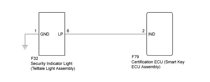
ENGINE IMMOBILISER SYSTEM (w/ Smart Key System) > Security Indicator Light Circuit |
| 1.PERFORM ACTIVE TEST USING TECHSTREAM (IMMOBILISER INDICATOR) |
Check that the security indicator light illuminates when operating it with the Active Test (Click here).
| Tester Display | Test Part | Control Range | Diagnostic Note |
| Immobiliser Indicator | Security indicator light | ON/OFF | The test is possible when the following conditions are met:
|
|
| ||||
| OK | ||
 | ||
| ||
| 2.INSPECT SECURITY INDICATOR LIGHT (TELLTALE LIGHT ASSEMBLY) |
Remove the security indicator light (telltale light assembly) (Click here).
Inspect the security indicator light (telltale light assembly) (Click here).
|
| ||||
| OK | |
 |
| 3.CHECK HARNESS AND CONNECTOR (TELLTALE LIGHT ASSEMBLY - CERTIFICATION ECU AND BODY GROUND) |
Disconnect the F32 security indicator light (telltale light assembly) connector.
Disconnect the F79 certification ECU (smart key ECU assembly) connector.
Measure the resistance according to the value(s) in the table below.
| Tester Connection | Condition | Specified Condition |
| F32-6 (LP) - F79-2 (IND) | Always | Below 1 Ω |
| F32-1 (GND) - Body ground | Always | Below 1 Ω |
| F32-6 (LP) or F79-2 (IND) - Body ground | Always | 10 kΩ or higher |
|
| ||||
| OK | ||
| ||
| ||

