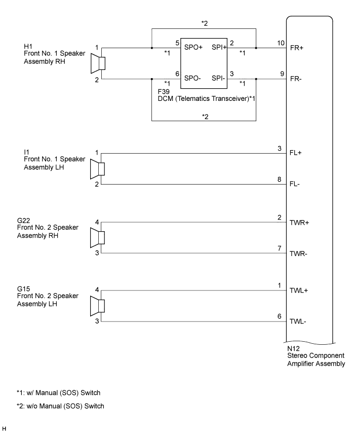
DTC B15C3 Speaker Output Short |
| DTC No. | DTC Detection Condition | Trouble Area |
| B15C3 | A short is detected in the speaker output circuit. |
|
| for 9 Speakers |
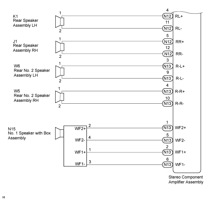
| for 8 Speakers |
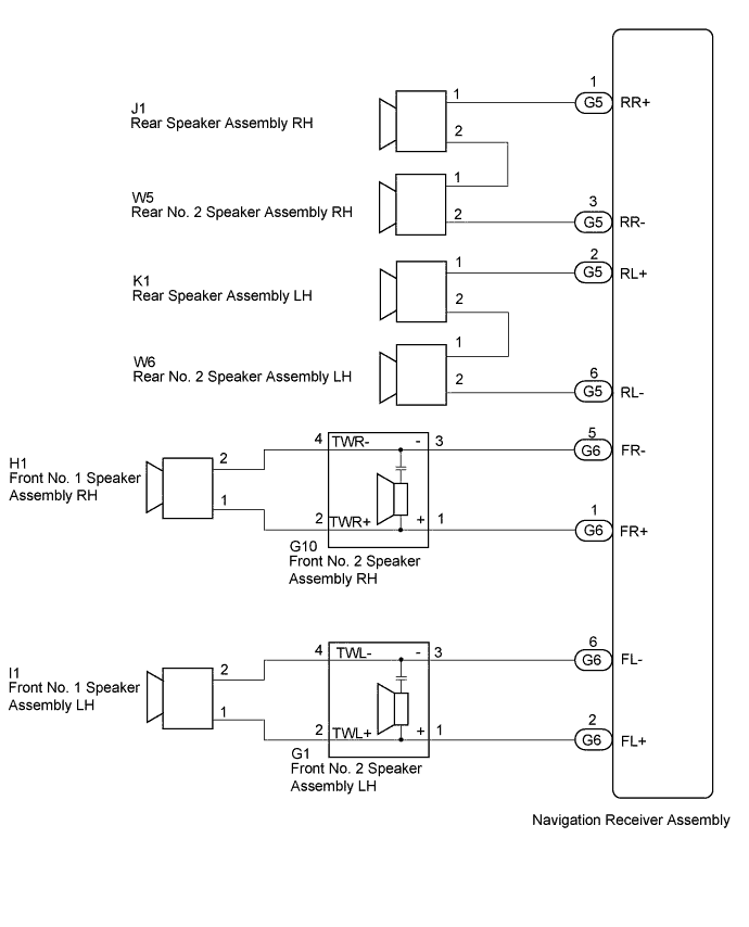
| 1.CHECK HARNESS AND CONNECTOR |
for 9 Speakers
Disconnect the N12 and N13 stereo component amplifier assembly connectors, F39 DCM (telematics transceiver)*1 connector and speaker assembly connectors.
Measure the resistance between the stereo component amplifier assembly and body ground to check for a short circuit in the wire harness.
| Tester Connection | Condition | Specified Condition |
| N12-10 (FR+) - Body ground | Always | 10 kΩ or higher |
| N12-9 (FR-) - Body ground | Always | 10 kΩ or higher |
| N12-3 (FL+) - Body ground | Always | 10 kΩ or higher |
| N12-8 (FL-) - Body ground | Always | 10 kΩ or higher |
| N12-2 (TWR+) - Body ground | Always | 10 kΩ or higher |
| N12-7 (TWR-) - Body ground | Always | 10 kΩ or higher |
| N12-1 (TWL+) - Body ground | Always | 10 kΩ or higher |
| N12-6 (TWL-) - Body ground | Always | 10 kΩ or higher |
| N12-4 (RL+) - Body ground | Always | 10 kΩ or higher |
| N12-11 (RL-) - Body ground | Always | 10 kΩ or higher |
| N12-5 (RR+) - Body ground | Always | 10 kΩ or higher |
| N12-12 (RR-) - Body ground | Always | 10 kΩ or higher |
| N13-3 (R-L+) - Body ground | Always | 10 kΩ or higher |
| N13-9 (R-L-) - Body ground | Always | 10 kΩ or higher |
| N13-4 (R-R+) - Body ground | Always | 10 kΩ or higher |
| N13-10 (R-R-) - Body ground | Always | 10 kΩ or higher |
| N13-1 (WF2+) - Body ground | Always | 10 kΩ or higher |
| N13-5 (WF2-) - Body ground | Always | 10 kΩ or higher |
| N13-2 (WF1+) - Body ground | Always | 10 kΩ or higher |
| N13-6 (WF1-) - Body ground | Always | 10 kΩ or higher |
w/ Manual (SOS) Switch
Measure the resistance between the DCM (telematics transceiver) and body ground to check for a short circuit in the wire harness.
| Tester Connection | Condition | Specified Condition |
| F39-5 (SPO+) - Body ground | Always | 10 kΩ or higher |
| F39-6 (SPO-) - Body ground | Always | 10 kΩ or higher |
for 8 speakers
Disconnect the G5 and G6 navigation receiver assembly connectors and speaker assembly connectors.
Measure the resistance between the navigation receiver assembly, speaker assembly and body ground to check for a short circuit in the wire harness.
| Tester Connection | Condition | Specified Condition |
| G6-1 (FR+) - Body ground | Always | 10 kΩ or higher |
| G6-5 (FR-) - Body ground | Always | 10 kΩ or higher |
| G6-2 (FL+) - Body ground | Always | 10 kΩ or higher |
| G6-6 (FL-) - Body ground | Always | 10 kΩ or higher |
| G5-1 (RR+) - Body ground | Always | 10 kΩ or higher |
| G5-3 (RR-) - Body ground | Always | 10 kΩ or higher |
| G5-2 (RL+) - Body ground | Always | 10 kΩ or higher |
| G5-6 (RL-) - Body ground | Always | 10 kΩ or higher |
| G10-2 (TWR+) - Body ground | Always | 10 kΩ or higher |
| G10-4 (TWR-) - Body ground | Always | 10 kΩ or higher |
| G1-2 (TWL+) - Body ground | Always | 10 kΩ or higher |
| G1-4 (TWR-) - Body ground | Always | 10 kΩ or higher |
| W6-1 - Body ground | Always | 10 kΩ or higher |
| W5-1 - Body ground | Always | 10 kΩ or higher |
|
| ||||
| OK | |
 |
| 2.INSPECT FRONT NO. 1 SPEAKER ASSEMBLY |
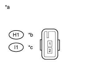 |
Measure the resistance according to the value(s) in the table below.
| Tester Connection | Condition | Specified Condition |
| H1-1 - H1-2 | Always | 1.4 to 2.2 Ω |
| I1-1 - I1-2 | Always | 1.4 to 2.2 Ω |
| Tester Connection | Condition | Specified Condition |
| H1-1 - H1-2 | Always | 4 Ω |
| I1-1 - I1-2 | Always | 4 Ω |
| *a | Component without harness connected (Front No. 1 Speaker Assembly) |
| *b | for RH |
| *c | for LH |
|
| ||||
| OK | |
|
| 3.REPLACE FRONT NO. 2 SPEAKER ASSEMBLY |
Replace the front No. 2 speaker assembly (Click here).
Clear the DTCs (Click here).
Recheck for DTCs and check if the same DTC are output again (Click here).
|
| ||||
| OK | ||
 | ||
| ||
| 4.CONFIRM MODEL |
Choose the model to be inspected.
| Model | Proceed to |
| for 9 Speakers | A |
| for 8 Speakers | B |
|
| ||||
| A | |
|
| 5.REPLACE REAR SPEAKER ASSEMBLY (for 9 Speakers) |
Replace the rear speaker assembly and check if the same DTC are output again.
Replace the rear speaker assembly (Click here).
Clear the DTCs (Click here).
Recheck for DTCs and check if the same DTC are output again (Click here).
|
| ||||
| OK | ||
| ||
| ||
| 6.REPLACE REAR NO. 2 SPEAKER ASSEMBLY (for 9 Speakers) |
Replace the rear No. 2 speaker assembly and check if the same DTC are output again.
Replace the rear No. 2 speaker assembly (Click here).
Clear the DTCs (Click here).
Recheck for DTCs and check if the same DTC are output again (Click here).
|
| ||||
| OK | ||
| ||
| ||
| 7.INSPECT REAR SPEAKER ASSEMBLY (for 8 Speakers) |
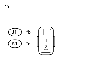 |
Measure the resistance according to the value(s) in the table below.
| Tester Connection | Condition | Specified Condition |
| J1-1 - J1-2 | Always | 4 Ω |
| K1-1 - K1-2 | Always | 4 Ω |
| *a | Component without harness connected (Rear Speaker Assembly) |
| *b | for RH |
| *c | for LH |
|
| ||||
| OK | |
|
| 8.INSPECT REAR NO. 2 SPEAKER ASSEMBLY (for 8 Speakers) |
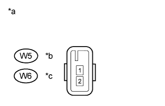 |
Measure the resistance according to the value(s) in the table below.
| Tester Connection | Condition | Specified Condition |
| W5-1 - W5-2 | Always | 4 Ω |
| W6-1 - W6-2 | Always | 4 Ω |
| *a | Component without harness connected (Rear No. 2 Speaker Assembly) |
| *b | for RH |
| *c | for LH |
|
| ||||
| OK | ||
| ||
| ||
| 9.INSPECT NO. 1 SPEAKER WITH BOX ASSEMBLY |
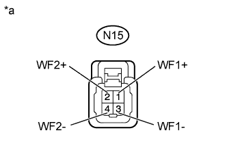 |
Measure the resistance according to the value(s) in the table below.
| Tester Connection | Condition | Specified Condition |
| N15-1 (WF1+) - N15-3 (WF1-) | Always | 1.6 to 2.4 Ω |
| N15-2 (WF2+) - N15-4 (WF2-) | Always | 1.6 to 2.4 Ω |
| *a | Component without harness connected (No. 1 Speaker with Box Assembly) |
| Condition | Proceed to |
| OK (w/ Manual (SOS) Switch) | A |
| OK (w/o Manual (SOS) Switch) | B |
| NG | C |
|
| ||||
|
| ||||
| A | |
|
| 10.INSPECT DCM (TELEMATICS TRANSCEIVER) |
Disconnect the F39 DCM (Telematics transceiver) connector.
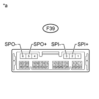 |
Measure the resistance according to the value(s) in the table below.
| Tester Connection | Condition | Specified Condition |
| F39-2 (SPI+) - F39-5 (SPO+) | Always | Below 1 Ω |
| F39-3 (SPI-) - F39-6 (SPO-) | Always | Below 1 Ω |
| F39-2 (SPI+) - F39-3 (SPI-) | Always | 10 kΩ or higher |
| F39-5 (SPO+) - F39-6 (SPO-) | Always | 10 kΩ or higher |
| F39-2 (SPI+) - Body ground | Always | 10 kΩ or higher |
| F39-3 (SPI-) - Body ground | Always | 10 kΩ or higher |
| *a | Component without harness connected (DCM (Telematics Transceiver)) |
|
| ||||
| OK | ||
| ||
| ||

