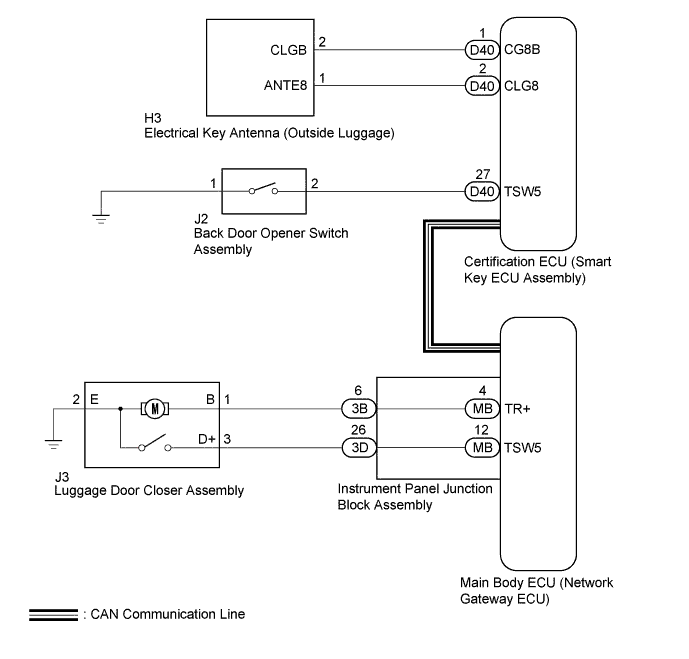
ENTRY AND START SYSTEM (for Entry Function) > Luggage Compartment Door Entry Unlock Function does not Operate when Key is Outside Luggage Compartment |
| 1.READ VALUE USING GTS (TRUNK OPEN MODE) |
Connect the GTS to the DLC3.
Turn the engine switch on (IG).
Turn the GTS on.
Enter the following menus: Body Electrical / Entry&Start / Data List.
Read the Data List according to the display on the GTS.
| Tester Display | Measurement Item/Range | Normal Condition | Diagnostic Note |
| Trunk Open Mode | Back door opener switch assembly / ON or OFF | Customization status displayed | - |
| Result | Proceed to |
| Entry luggage compartment door open mode is ON | A |
| Entry luggage compartment door open mode is OFF | B |
|
| ||||
| A | |
 |
| 2.READ VALUE USING GTS (TR/B-DOOR UNLOCK SW) |
Connect the GTS to the DLC3.
Turn the engine switch on (IG).
Turn the GTS on.
Enter the following menus: Body Electrical / Entry&Start / Data List.
Read the Data List according to the display on the GTS.
| Tester Display | Measurement Item/Range | Normal Condition | Diagnostic Note |
| Tr/B-Door Unlock SW | Back door opener switch assembly / ON or OFF | ON: Back door opener switch assembly pushed OFF: Back door opener switch assembly not pushed | - |
|
| ||||
| OK | |
|
| 3.PERFORM ACTIVE TEST USING GTS (TRUNK AND BACK-DOOR OPEN) |
Connect the GTS to the DLC3.
Turn the engine switch on (IG).
Turn the GTS on.
Enter the following menus: Body Electrical / Main Body / Active Test.
Read the Data List according to the display on the GTS.
| Tester Display | Test Part | Control Range | Diagnostic Note |
| Trunk and Back-door Open | Operate luggage door closer assembly motor | ON/OFF | - |
|
| ||||
| OK | |
|
| 4.CHECK WAVE ENVIRONMENT |
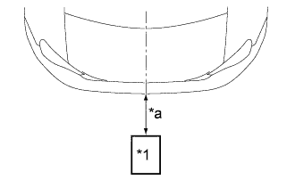 |
Bring the electrical key transmitter sub-assembly near the electrical key antenna (outside luggage), and perform an entry luggage compartment open function check.
| *1 | Electrical Key Transmitter Sub-assembly |
| *a | Approximately 0.3 m (0.984 ft.) |
|
| ||||
| OK | ||
 | ||
| ||
| 5.CHECK KEY DIAGNOSTIC MODE |
|
Check the following antennas in the key diagnostic mode (Click here).
| *1 | Electrical Key Transmitter Sub-assembly |
| *a | 0.7 to 1.0 m (2.30 to 3.28 ft.) |
When the electrical key transmitter sub-assembly is held at the same height as the rear bumper upper surface, align it with the center of the rear of the vehicle and check that the wireless door lock buzzer sounds.
|
| ||||
| OK | ||
| ||
| ||
| 6.CHECK HARNESS AND CONNECTOR CERTIFICATION ECU (SMART KEY ECU ASSEMBLY) - ELECTRICAL KEY ANTENNA) |
Disconnect the D40 certification ECU (smart key ECU assembly) connector.
Disconnect the H3 electrical key antenna (outside luggage) connector.
Measure the resistance according to the value(s) in the table below.
| Tester Connection | Condition | Specified Condition |
| D40-1 (CG8B) - H3-2 (CLGB) | Always | Below 1 Ω |
| D40-2 (CLG8) - H3-1 (ANTE8) | Always | Below 1 Ω |
| Tester Connection | Condition | Specified Condition |
| D40-1 (CG8B) or H3-2 (CLGB) - Body ground | Always | 10 kΩ or higher |
| D40-2 (CLG8) or H3-1 (ANTE8) - Body ground | Always | 10 kΩ or higher |
|
| ||||
| OK | |
|
| 7.INSPECT ELECTRICAL KEY ANTENNA (OUTSIDE LUGGAGE) |
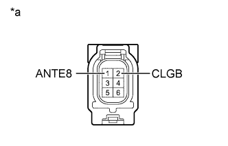 |
Remove the electrical key antenna (outside luggage) (Click here)
Measure the resistance according to the value(s) in the table below.
| Tester Connection | Condition | Specified Condition |
| 1 (ANTE8) - 2 (CLGB) | Always | Below 1 Ω |
| *a | Component without harness connected: (Electrical Key Antenna (Outside Luggage)) |
|
| ||||
| OK | ||
| ||
| ||
| 8.INSPECT BACK DOOR OPENER SWITCH ASSEMBLY |
Remove the back door opener switch assembly (Click here).
Inspect the back door opener switch assembly (Click here).
|
| ||||
| OK | |
|
| 9.CHECK HARNESS AND CONNECTOR CERTIFICATION ECU (SMART KEY ECU ASSEMBLY) - BACK DOOR OPENER SWITCH ASSEMBLY) |
Disconnect the D40 certification ECU (smart key ECU assembly) connector.
Disconnect the J2 back door opener switch assembly connector.
Measure the resistance according to the value(s) in the table below.
| Tester Connection | Condition | Specified Condition |
| D40-27 (TSW5) - J2-2 | Always | Below 1 Ω |
| J2-1 - Body ground | Always | Below 1 Ω |
| Tester Connection | Condition | Specified Condition |
| D40-27 (TSW5) or J2-2 - Body ground | Always | 10 kΩ or higher |
|
| ||||
| OK | ||
| ||
| ||
| 10.INSPECT LUGGAGE DOOR CLOSER ASSEMBLY |
Remove the luggage door closer assembly (Click here).
Inspect the luggage door closer assembly (Click here).
|
| ||||
| OK | |
|
| 11.CHECK HARNESS AND CONNECTOR (INSTRUMENT PANEL JUNCTION BLOCK ASSEMBLY - LUGGAGE DOOR CLOSER ASSEMBLY) |
Disconnect the 3B and 3D instrument panel junction block assembly connectors.
Disconnect the J3 luggage door closer assembly connector.
Measure the resistance according to the value(s) in the table below.
| Tester Connection | Condition | Specified Condition |
| 3B-6 - J3-1 (B) | Always | Below 1 Ω |
| 3D-26 - J3-3 (D+) | Always | Below 1 Ω |
| J3-2 (E) - Body ground | Always | Below 1 Ω |
| Tester Connection | Condition | Specified Condition |
| 3B-6 or J3-1 (B) - Body ground | Always | 10 kΩ or higher |
| 3D-26 or J3-3 (D+) - Body ground | Always | 10 kΩ or higher |
|
| ||||
| OK | |
|
| 12.REPLACE INSTRUMENT PANEL JUNCTION BLOCK ASSEMBLY |
Replace the instrument panel junction block assembly with a new one (Click here).
| NEXT | |
|
| 13.CHECK OPERATION |
Check that the luggage compartment open functions operate normally (Click here).
|
| ||||
| OK | ||
| ||
| ||

