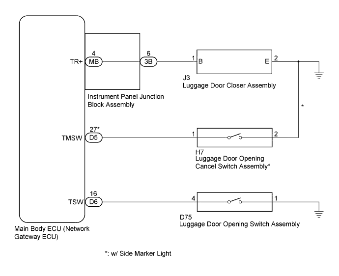
LUGGAGE COMPARTMENT DOOR OPENER SYSTEM > Luggage Compartment Door Opener does not Operate |
| 1.PERFORM ACTIVE TEST USING GTS |
Connect the GTS to the DLC3.
Turn the ignition switch to ON.
Turn the GTS on.
Enter the following menus: Body Electrical / Main Body / Active Test.
Perform the Active Test according to the display on the GTS.
| Tester Display | Test Part | Control Range | Diagnostic Note |
| Trunk and Back-Door Open | Operate luggage compartment door lock motor | ON/OFF | This test will open the trunk |
|
| ||||
| OK | |
 |
| 2.CHECK VEHICLE SPECIFICATIONS |
Check the vehicle specifications.
| Result | Proceed to |
| w/ Side Marker Light | A |
| w/o Side Marker Light | B |
|
| ||||
| A | |
|
| 3.CHECK LUGGAGE COMPARTMENT DOOR OPENER SYSTEM (LUGGAGE DOOR OPENING CANCEL SWITCH ASSEMBLY) |
When the luggage door opening cancel switch assembly is on, push the luggage door opening switch assembly and check that the luggage compartment door opens.
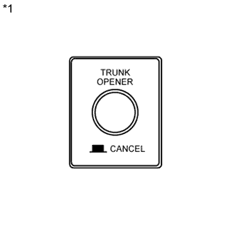 |
When the luggage door opening cancel switch assembly is off, push the luggage door opening switch assembly and check that the luggage compartment door does not open.
| *1 | Luggage Door Opening Cancel Switch Assembly |
| Result | Proceed to |
| NG | A |
| OK | B |
|
| ||||
| A | |
|
| 4.READ VALUE USING GTS |
Connect the GTS to the DLC3.
Turn the ignition switch to ON.
Turn the GTS on.
Enter the following menus: Body Electrical / Main Body / Data List.
Read the Data List according to the display on the GTS.
| Tester Display | Measurement Item/Range | Normal Condition | Diagnostic Note |
| Trunk/BDoor Open SW | Luggage door opening switch signal/ON or OFF | ON: Luggage door opening switch assembly is pushed OFF: Luggage door opening switch assembly is not pushed | - |
| Trunk Main SW | Luggage door opening cancel switch signal/ON or OFF | ON: Luggage door opening cancel switch assembly is pushed OFF: Luggage door opening cancel switch assembly is not pushed | - |
| Result | Proceed to |
| NG (Luggage door opening cancel switch assembly is abnormal) | A |
| NG (Luggage door opening switch assembly is abnormal) | B |
| OK | C |
|
| ||||
|
| ||||
| A | |
|
| 5.INSPECT LUGGAGE DOOR OPENING CANCEL SWITCH ASSEMBLY |
Remove the luggage door opening cancel switch assembly (Click here).
Inspect the luggage door opening cancel switch assembly (Click here).
|
| ||||
| OK | |
|
| 6.CHECK HARNESS AND CONNECTOR (LUGGAGE DOOR OPENING CANCEL SWITCH ASSEMBLY - MAIN BODY ECU (NETWORK GATEWAY ECU)) |
Disconnect the D5 main body ECU (network gateway ECU) connector and the H7 luggage door opening cancel switch assembly.
Measure the resistance according to the value(s) in the table below.
| Tester Connection | Condition | Specified Condition |
| D5-27 (TMSW) - H7-1 | Always | Below 1 Ω |
| H7-2 - Body ground | Always | Below 1 Ω |
| Tester Connection | Condition | Specified Condition |
| D5-27 (TMSW) - Body ground | Always | 10 kΩ or higher |
|
| ||||
| OK | ||
 | ||
| ||
| 7.READ VALUE USING GTS |
Connect the GTS to the DLC3.
Turn the ignition switch to ON.
Turn the GTS on.
Enter the following menus: Body Electrical / Main Body / Data List.
Read the Data List according to the display on the GTS.
| Tester Display | Measurement Item/Range | Normal Condition | Diagnostic Note |
| Trunk/BDoor Open SW | Luggage door opening switch signal/ON or OFF | ON: Luggage door opening switch assembly is pushed OFF: Luggage door opening switch assembly is not pushed | - |
| Result | Proceed to |
| NG | A |
| OK | B |
|
| ||||
| A | |
|
| 8.INSPECT LUGGAGE DOOR OPENING SWITCH ASSEMBLY |
Remove the luggage door opening switch assembly (Click here).
Inspect the luggage door opening switch assembly (Click here).
|
| ||||
| OK | |
|
| 9.CHECK HARNESS AND CONNECTOR (LUGGAGE DOOR OPENING SWITCH ASSEMBLY - MAIN BODY ECU (NETWORK GATEWAY ECU)) |
Disconnect the D6 main body ECU (network gateway ECU) connector and the D75 luggage door opening switch assembly.
Measure the resistance according to the value(s) in the table below.
| Tester Connection | Condition | Specified Condition |
| D6-16 (TSW) - D75-4 | Always | Below 1 Ω |
| D75-1 - Body ground | Always | Below 1 Ω |
| Tester Connection | Condition | Specified Condition |
| D6-16 (TSW) - Body ground | Always | 10 kΩ or higher |
|
| ||||
| OK | ||
| ||
| ||
| 10.INSPECT LUGGAGE DOOR CLOSER ASSEMBLY |
Remove the luggage door closer assembly (Click here).
Inspect the luggage door closer assembly (Click here).
|
| ||||
| OK | |
|
| 11.CHECK HARNESS AND CONNECTOR (LUGGAGE DOOR CLOSER ASSEMBLY - INSTRUMENT PANEL JUNCTION BLOCK ASSEMBLY) |
Disconnect the 3B instrument panel junction block assembly connector and the J3 luggage door closer assembly.
Measure the resistance according to the value(s) in the table below.
| Tester Connection | Condition | Specified Condition |
| J3-1 (B) - 3B-6 | Always | Below 1 Ω |
| J3-2 (E) - Body ground | Always | Below 1 Ω |
| Tester Connection | Condition | Specified Condition |
| J3-1 (B) - Body ground | Always | 10 kΩ or higher |
|
| ||||
| OK | |
|
| 12.REPLACE INSTRUMENT PANEL JUNCTION BLOCK ASSEMBLY |
Temporarily replace the instrument panel junction block assembly with a new or normally functioning one (Click here).
Check the luggage door closer assembly operation.
|
| ||||
| OK | ||
| ||
| ||

