FA20 ENGINE MECHANICAL VALVE CLEARANCE ADJUSTMENT
PROCEDURE

 19500
1.REMOVE IGNITION COIL ASSEMBLY
23261A
2.REMOVE INJECTOR COVER (for Bank 1)
89879
3.REMOVE INJECTOR DRIVER BRACKET
11201
4.REMOVE CYLINDER HEAD COVER SUB-ASSEMBLY RH
11202
5.REMOVE CYLINDER HEAD COVER SUB-ASSEMBLY LH
6.INSPECT VALVE CLEARANCE
- NOTICE:
-
Inspect the valve clearance when the engine is cold.
Set the No. 1 cylinder to the TDC/compression.
Turn the crankshaft clockwise to align the timing mark on the crankshaft pulley with the indicator of the timing chain cover.
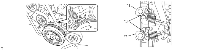
| *1 | Intake Camshaft | *2 | Exhaust Camshaft |
| *3 | No. 1 Valve Rocker Arm Sub-assembly | - | - |
| *a | Timing Mark | - | - |
At this time, check that the intake camshaft and exhaust camshaft do not depress the No. 1 cylinder intake side No. 1 valve rocker arm sub-assembly (intake valve) and exhaust side No. 1 valve rocker arm sub-assembly (exhaust valve).
- HINT:
-
If the No. 1 valve rocker arm sub-assembly (valve) is depressed, turn the crank pulley by 360° in order to make the No. 1 cylinder piston at TDC/compression.
Inspect the valve clearance indicated in the illustration.
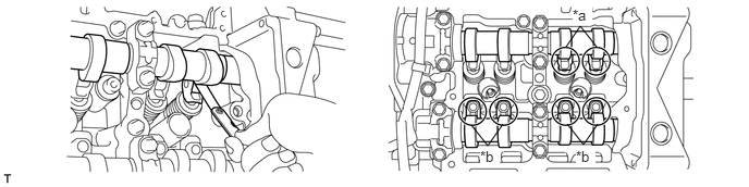
| *a | Intake Side | *b | Exhaust Side |
Measure the clearance between the surface of the cam base circle and the roller surface of the No. 1 valve rocker arm sub-assembly using a feeler gauge.
- Standard Calve Clearance (Cold):
Intake 0.10 to 0.16 mm (0.0039 to 0.0063 in.)
Exhaust 0.21 to 0.27 mm (0.0083 to 0.0106 in.)
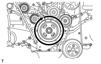
Turn the crank pulley by 360°.
Inspect the valve clearance indicated in the illustration.
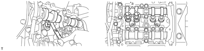
| *a | Intake Side | - | - |
Measure the clearance between the surface of the cam base circle and the roller surface of the No. 1 valve rocker arm sub-assembly using a feeler gauge.
- Standard Calve Clearance (Cold):
Intake 0.10 to 0.16 mm (0.0039 to 0.0063 in.)
Turn the crank pulley clockwise, set the No. 2 cylinder at TDC/compression, and then align the timing mark (notch) with 0° position of the timing chain cover.
| *1 | Intake Camshaft | *2 | Exhaust Camshaft |
| *3 | No. 1 Valve Rocker Arm Sub-assembly | - | - |
| *a | Timing Mark | - | - |
At this time, check that the intake camshaft and exhaust camshaft do not depress the No. 2 cylinder intake side No. 1 valve rocker arm sub-assembly (intake valve) and exhaust side No. 1 valve rocker arm sub-assembly (exhaust valve).
- HINT:
-
If the No. 1 valve rocker arm sub-assembly (valve) is depressed, turn the crank pulley by 360° in order to make the No. 2 cylinder piston at TDC/compression.
Inspect the valve clearance indicated in the illustration.
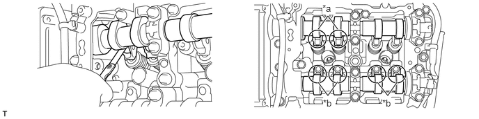
| *a | Intake Side | *b | Exhaust Side |
Measure the clearance between the surface of the cam base circle and the roller surface of the No. 1 valve rocker arm sub-assembly using a feeler gauge.
- Standard Calve Clearance (Cold):
Intake 0.10 to 0.16 mm (0.0039 to 0.0063 in.)
Exhaust 0.21 to 0.27 mm (0.0083 to 0.0106 in.)
Turn the crank pulley by 360°.
Inspect the valve clearance indicated in the illustration.
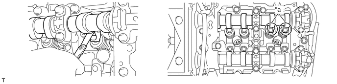
| *a | Intake Side | - | - |
Measure the clearance between the surface of the cam base circle and the roller surface of the No. 1 valve rocker arm sub-assembly using a feeler gauge.
- Standard Calve Clearance (Cold):
Intake 0.10 to 0.16 mm (0.0039 to 0.0063 in.)
7.ADJUST VALVE CLEARANCE
Remove the camshaft housing sub-assembly.
(See page Engine / Hybrid System>FA20 (ENGINE MECHANICAL)>ENGINE UNIT>DISASSEMBLY)
Remove the No. 1 valve rocker arm sub-assemblies.
Remove the valve adjusting shims.
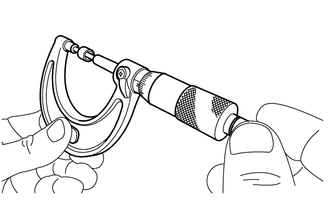
Using a micrometer, measure the thickness of the removed valve adjusting shims.
Calculate the thickness of the valve adjusting shim so that the valve clearance comes within the specified values.
- Intake Side:
A = B + [C - 0.13 mm (0.0051 in.)] x 1.54
- Exhaust Side:
A = B + [C - 0.24 mm (0.0094 in.)] x 1.69
- A:
Required valve adjusting shim thickness
- B:
Removed valve adjusting shim thickness
- C:
Measured valve clearance
Apply engine oil to the inner face of the valve adjusting shim, and install it to the valve.
- NOTICE:
-
Check whether valve adjusting shim can be rotated smoothly on the valve.
Install the No. 1 valve rocker arm sub-assemblies.
Install the camshaft housing sub-assembly.
(See page Engine / Hybrid System>FA20 (ENGINE MECHANICAL)>ENGINE UNIT>REASSEMBLY)
11202
8.INSTALL CYLINDER HEAD COVER SUB-ASSEMBLY LH
11201
9.INSTALL CYLINDER HEAD COVER SUB-ASSEMBLY RH
89879
10.INSTALL INJECTOR DRIVER BRACKET
23261A
11.INSTALL INJECTOR COVER (for Bank 1)
19500
12.INSTALL IGNITION COIL ASSEMBLY