FA20 INTAKE / EXHAUST INTAKE MANIFOLD REMOVAL
PROCEDURE

 1.CHECK FUEL PUMP OPERATION AND INSPECT FOR FUEL LEAK
2.DISCONNECT CABLE FROM NEGATIVE BATTERY TERMINAL
3.REMOVE AIR CLEANER CAP WITH AIR CLEANER HOSE
22030
4.REMOVE THROTTLE WITH MOTOR BODY ASSEMBLY
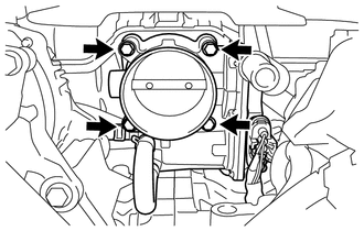
Remove the 4 bolts and disconnect the throttle with motor body assembly.
Remove the gasket.
89871
5.REMOVE INJECTOR DRIVER
23261A
6.REMOVE INJECTOR COVER (for Bank 2)
23261A
7.REMOVE INJECTOR COVER (for Bank 1)
8.DISCONNECT NO. 1 FUEL HOSE (for Clamp Type)
77259D
9.DISCONNECT NO. 1 FUEL HOSE (for Metal Type)
23807
10.DISCONNECT FUEL DELIVERY PIPE SUB-ASSEMBLY
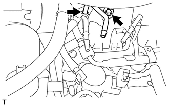
Remove the bolt and disconnect the fuel delivery pipe sub-assembly.
Disconnect the No. 2 fuel vapor feed hose and move the fuel delivery pipe toward the front of the vehicle.
12601B
11.REMOVE NO. 1 ENGINE COVER SUB-ASSEMBLY (for Resin Intake Manifold)
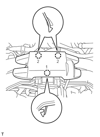
Disengage the 3 craws and remove the No. 1 engine cover sub-assembly.
- HINT:
-
Disengage the 3 craws in the order shown in the illustration.
16361A
12.REMOVE FAN AND GENERATOR V BELT (for Aluminum Intake Manifold)
13.DISCONNECT COMPRESSOR WITH MAGNETIC CLUTCH (for Aluminum Intake Manifold)
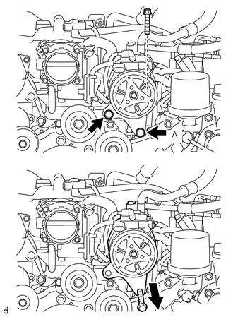
Remove the 3 bolts and hold the compressor with magnetic clutch by hand.
Temporarily install a bolt with length of approximately 100 mm (3.937 in) to the position A, and move the compressor with magnetic clutch forward.
44771
14.DISCONNECT VACUUM TUBE CONNECTOR HOSE (for Manual Transmission)
12261
15.DISCONNECT VENTILATION HOSE
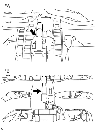
Disconnect the ventilation hose.
| *A | for Resin Intake Manifold |
| *B | for Aluminum Intake Manifold |
17111
16.REMOVE INTAKE MANIFOLD
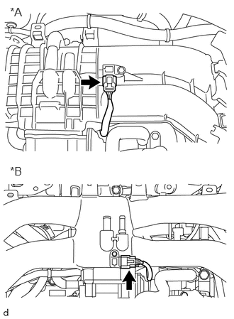
Disconnect the manifold absolute pressure sensor connector.
| *A | for Resin Intake Manifold |
| *B | for Aluminum Intake Manifold |
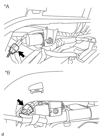
Disconnect the purge valve connector.
| *A | for Resin Intake Manifold |
| *B | for Aluminum Intake Manifold |
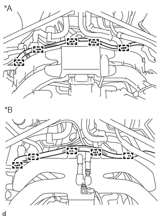
Disengage the 5 clamps and disconnect the battery cable. (for RHD)
| *A | for Resin Intake Manifold |
| *B | for Aluminum Intake Manifold |
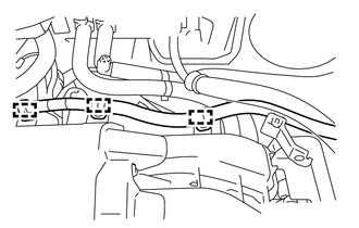
Disengage the 3 clamps and disconnect the wire harness. (for LHD)
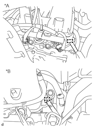
Disengage the clamp and disconnect the engine wire harness.
| *A | for Resin Intake Manifold |
| *B | for Aluminum Intake Manifold |
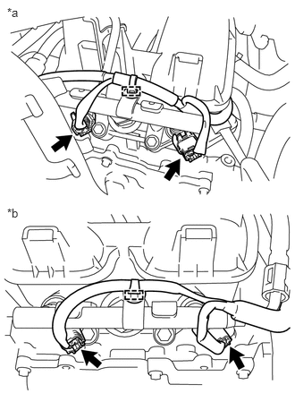
Disengage the 2 clamps and disconnect the 4 connectors.
| *a | for Bank 2 |
| *b | for Bank 1 |
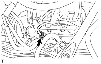
Disconnect the fuel pump connector.
for Resin Intake Manifold:
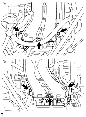
Remove the 6 bolts, intake manifold and 2 gaskets.
| *a | for Bank 2 |
| *b | for Bank 1 |
for Aluminum Intake Manifold:
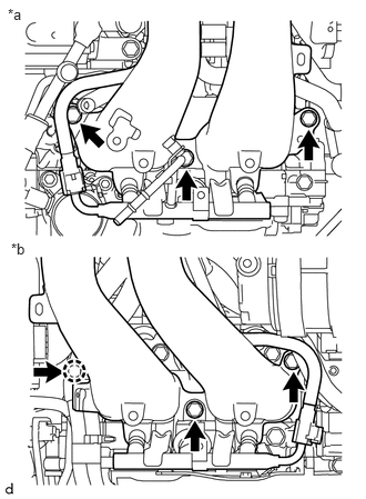
Remove the 6 bolts, intake manifold and 2 gaskets.
| *a | for Bank 2 |
| *b | for Bank 1 |