FA20 COOLING RADIATOR INSTALLATION
PROCEDURE

 16468
1.INSTALL RADIATOR PACKING (LOWER)
Install the new radiator packing.
16465B
2.INSTALL NO. 2 RADIATOR PACKING
Install the new No. 2 radiator packing.
16465A
3.INSTALL NO. 1 RADIATOR PACKING
Install the new No. 1 radiator packing.
16465
4.INSTALL RADIATOR PACKING (UPPER)
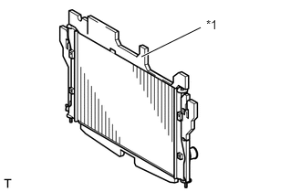
Install the new radiator packing.
| *1 | Radiator Packing |
- HINT:
-
Cut the radiator packing at the same position in the removal.
16572
5.INSTALL OUTLET RADIATOR HOSE
Since the radiator hose must be attached in the correct position, apply match marks before removing it.
Install the outlet radiator hose to the radiator assembly and secure it with the clamp.
16571C
6.INSTALL NO. 1 RADIATOR HOSE
Since the radiator hose must be attached in the correct position, apply match marks before removing it.
Install the No. 1 radiator hose to the water filler sub-assembly and secure it with the clamp.
16571
7.INSTALL INLET RADIATOR HOSE
Since the radiator hose must be attached in the correct position, apply match marks before removing it.
Install the inlet radiator hose to the radiator assembly and secure it with the clamp.
16400
8.INSTALL RADIATOR ASSEMBLY
Install the 2 radiator support cushions to the radiator assembly.
While lifting the outlet radiator hose, install the radiator assembly.
- NOTICE:
-
Push a blanket or a cardboard against the cooler condenser assembly to protect it.
Attach the claw and install the thermistor assembly.
Install the radiator support RH with the 2 bolts.
- Torque:
- 7.5 N*m (76 kgf*cm, 66 in.*lbf)
Install the radiator support LH with the 2 bolts.
- Torque:
- 7.5 N*m (76 kgf*cm, 66 in.*lbf)
16711
9.INSTALL FAN SHROUD
88460
10.INSTALL COOLER CONDENSER ASSEMBLY
Install the cooler condenser assembly to the radiator assembly with the 5 bolts.
- Torque:
- 6.0 N*m (61 kgf*cm, 53 in.*lbf)
53201
11.INSTALL RADIATOR SUPPORT SUB-ASSEMBLY
Install the 6 bolts and radiator support sub-assembly.
- Torque:
- 18 N*m (184 kgf*cm, 13 ft.*lbf)
53510
12.INSTALL HOOD LOCK ASSEMBLY (for LHD)
53510
13.INSTALL HOOD LOCK ASSEMBLY (for RHD)
16502
14.INSTALL WATER FILLER SUB-ASSEMBLY
Install the water filler sub-assembly and water filler bracket with the 4 bolts.
- Torque:
- 7.5 N*m (76 kgf*cm, 66 in.*lbf)
Connect the inlet radiator hose and No. 1 radiator hose to the radiator assembly with the 2 clamps.
Connect the radiator cap hose to the water filler sub-assembly.
53291B
15.INSTALL RADIATOR COVER PLATE
Install the radiator cover plate with the 6 clips.
17764
16.INSTALL AIR CLEANER DUCT
Install the air cleaner duct with the 2 bolts.
- Torque:
- 6.0 N*m (61 kgf*cm, 53 in.*lbf)
16470
17.INSTALL RADIATOR RESERVE TANK ASSEMBLY
Install the radiator reserve tank assembly with the 2 bolts.
- Torque:
- 7.5 N*m (76 kgf*cm, 66 in.*lbf)
16572
18.CONNECT OUTLET RADIATOR HOSE
19.ADD ENGINE COOLANT
20.INSPECT FOR COOLANT LEAK
51441
21.INSTALL NO. 1 ENGINE UNDER COVER
52119A
22.INSTALL FRONT BUMPER COVER
17701
23.INSTALL AIR CLEANER CASE SUB-ASSEMBLY
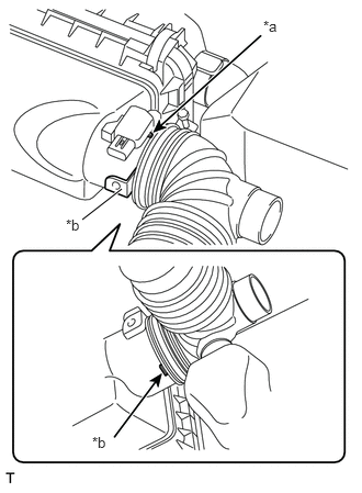
Connect the hose.
- Torque:
- 3.0 N*m (31 kgf*cm, 27 in.*lbf)
- HINT:
-
When connecting the hose, align the protrusion of the air cleaner case sub-assembly with the cutout of the hose, and push in the hose until it contacts the stopper of the air cleaner case sub-assembly.
| *a | match marks |
| *b | Stopper |