TL70 MANUAL TRANSMISSION / TRANSAXLE SHIFT LEVER ASSEMBLY INSTALLATION
PROCEDURE

 33511G
1.INSTALL CONTROL SHAFT
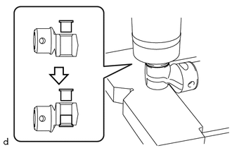
While holding the collar with your hand, press the collar slowly straight into the control shaft hole using a press.
- NOTICE:
-
Be careful that your hand does not get caught.
- HINT:
-
Use the same procedure as above to press-fit the other collar from the opposite end of the control shaft.
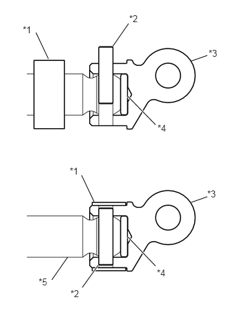
Install a new control shaft collar onto the shift shaft.
Install the shift lever damper and control shaft to the shift shaft.
Using a pin punch (5 mm (0.197 in.)) and a hammer, align the control shaft hole and the shift shaft hole with the cutout of the control shaft collar, and insert the shaft pin from above.
Slide the control shaft collar until it comes into contact with the stopper of the control shaft, then stake it to the cutout.
| *1 | Control Shaft Collar |
| *2 | Shaft Pin |
| *3 | Control Shaft |
| *4 | Shift Lever Damper |
| *5 | Shift Shaft |
33511
2.INSTALL FLOOR SHIFT CONTROL SHAFT
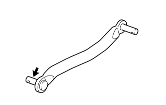
Apply a light coat of MP grease to the floor shift control shaft.

|
MP grease |
Install the plate washer and clip.
3.INSTALL SHIFT LEVER RETAINER BUSHING
Install the 4 shift lever retainer bushings to the floor shift control shift lever retainer.
33575
4.INSTALL FLOOR SHIFT CONTROL SHIFT LEVER RETAINER
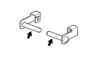
Apply a light coat of MP grease to new 2 shift lever pins.
|
|
MP grease |
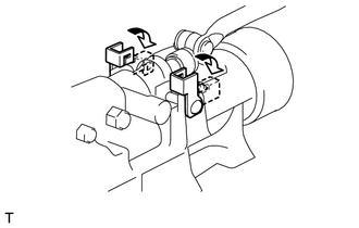
Install the floor shift control shift lever retainer with the 2 shift lever pins.
Secure the shift lever pins to the extension housing sub-assembly.
5.INSTALL MANUAL TRANSMISSION ASSEMBLY
33555B
6.INSTALL SHIFT AND SELECT LEVER BOOT
Temporarily install a new shift and select lever boot to the floor shift lever assembly.
33530F
7.INSTALL FLOOR SHIFT LEVER ASSEMBLY
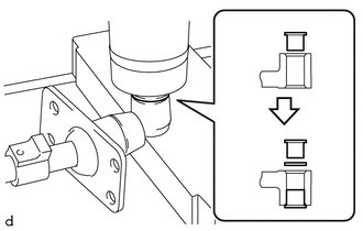
While holding the collar with your hand, press the collar slowly straight into the floor shift lever assembly hole using a press.
- NOTICE:
-
Be careful that your hand does not get caught.
Install the O-ring to the floor shift lever assembly.
While holding the collar with your hand, press the collar slowly straight into the floor shift lever assembly hole using a press.
- NOTICE:
-
Be careful that your hand does not get caught.
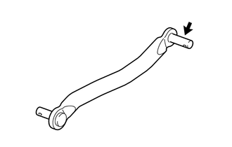
Apply a light coat of MP grease to the floor shift control shaft.
|
|
MP grease |
Install the plate washer to the floor shift lever assembly.
Install the shift lever assembly with the clip.
Install the shift and select lever boot.
- NOTICE:
-
Do not damage the shift and select lever boot.
33506F
8.INSTALL FLOOR SHIFT CONTROL SHIFT LEVER RETAINER SUB-ASSEMBLY
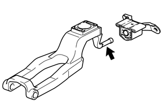
Apply a light coat of MP grease to the floor shift control shift lever retainer sub-assembly.
|
|
MP grease |
Install the floor shift control shift lever retainer sub-assembly to the floor shift control shift lever retainer.
Install the floor shift control shift lever retainer sub-assembly with the 2 bolts.
- Torque:
- 18 N*m (184 kgf*cm, 13 ft.*lbf)
37100
9.INSTALL PROPELLER SHAFT WITH CENTER BEARING ASSEMBLY
33554
10.INSTALL SHIFT LEVER CAP
Install the shift lever cap with the 4 bolts.
- Torque:
- 7.5 N*m (76 kgf*cm, 66 in.*lbf)
11.ADJUST SHIFT LEVER POSITION
33555
12.INSTALL SHIFT LEVER BOOT
Install the shift lever boot and shift and select lever retainer with the 4 bolts.
- Torque:
- 18 N*m (184 kgf*cm, 13 ft.*lbf)
Connect the wire harness clamp.
Install the shift and select lever cover with the 2 clips.
58810J
13.INSTALL CONSOLE BOX ASSEMBLY
14.CONNECT CABLE TO NEGATIVE BATTERY TERMINAL