HEATING / AIR CONDITIONING AIR CONDITIONING UNIT INSTALLATION
PROCEDURE

 87010
1.INSTALL AIR CONDITIONING UNIT ASSEMBLY (for Automatic Air Conditioning System)
Install the 3 bolts and 3 nuts.
- Torque:
- 7.5 N*m (76 kgf*cm, 66 in.*lbf)
Engage the drain cooler hose.
Connect each connector and engage each clamp and install the air conditioning unit assembly.
87010
2.INSTALL AIR CONDITIONING UNIT ASSEMBLY (for Manual Air Conditioning System)
- HINT:
-
Use the same procedure as for the automatic air conditioning system.
87010
3.INSTALL AIR CONDITIONING UNIT ASSEMBLY (w/o Air Conditioning System)
- HINT:
-
Use the same procedure as for the automatic air conditioning system.
55330B
4.INSTALL INSTRUMENT PANEL REINFORCEMENT ASSEMBLY
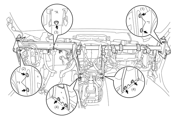
| *A | for RHD | - | - |
| *1 | "TORX" Bolt | - | - |
Using a 4 mm "TORX" wrench, install the 4 "TORX" Bolts in the order shown in the illustration.
- Torque:
- 25 N*m (255 kgf*cm, 18 ft.*lbf)
Install the instrument panel reinforcement assembly with the 5 bolts in the order shown in the illustration.
- Torque:
- 25 N*m (255 kgf*cm, 18 ft.*lbf)
Connect each connector and engage each clamp.
Connect the 2 earth wires with the 2 bolts.
62112
5.INSTALL COWL SIDE TRIM BOARD LH
62111C
6.INSTALL COWL SIDE TRIM BOARD RH
67914
7.INSTALL FRONT DOOR SCUFF PLATE LH
67913
8.INSTALL FRONT DOOR SCUFF PLATE RH
45250
9.INSTALL STEERING COLUMN ASSEMBLY
73900
10.INSTALL LOWER NO. 1 INSTRUMENT PANEL AIR BAG ASSEMBLY (w/ Knee Airbag)
55302C
11.INSTALL INSTRUMENT PANEL SUB-ASSEMBLY
88790E
12.CONNECT AIR CONDITIONER TUBE AND ACCESSORY ASSEMBLY
Remove the vinyl tape from the pipe.
Sufficiently apply compressor oil to a new O-ring and fitting surface of the air conditioner tube and accessory assembly.
- Compressor oil:
- for HFC-134a (R134a):
ND-OIL 8 or equivalent
- for HFO-1234yf (R1234yf):
ND-OIL 12 or equivalent
Install the O-ring to the air conditioner tube and accessory assembly.
Install the air conditioner tube and accessory assembly.
88704
13.CONNECT SUCTION HOSE SUB-ASSEMBLY
Remove the vinyl tape from the pipe.
Sufficiently apply compressor oil to a new O-ring and the fitting surface of the suction hose sub-assembly.
- Compressor oil:
- for HFC-134a (R134a):
ND-OIL 8 or equivalent
- for HFO-1234yf (R1234yf):
ND-OIL 12 or equivalent
Connect the O-ring to the suction hose sub-assembly.
Connect the suction hose sub-assembly.
Rotate the hook connector in the direction indicated by the arrow in the illustration.
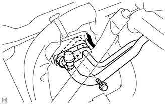
Insert the pipe joint into the cooler expansion valve securely and tighten the bolt.
- Torque:
- 7.5 N*m (76 kgf*cm, 66 in.*lbf)
87246A
14.CONNECT OUTLET HEATER WATER HOSE A
Install the outlet heater water hose A and attach the clip.
- HINT:
-
Install the outlet heater water hose A while aligning it with the matching marks made when it was removed.
87245A
15.CONNECT INLET HEATER WATER HOSE A
Install the inlet heater water hose A and attach the clip.
- HINT:
-
Install the inlet heater water hose A while aligning it with the matching marks made when it was removed.
16.CONNECT CABLE TO NEGATIVE BATTERY TERMINAL
- Torque:
- 6.0 N*m (61 kgf*cm, 53 in.*lbf)
17.ADD ENGINE COOLANT
18. CHARGE AIR CONDITIONING SYSTEM WITH REFRIGERANT
for HFC-134a (R134a):
(See page Vehicle Interior>HEATING / AIR CONDITIONING>REFRIGERANT(for HFC-134a(R134a))>REPLACEMENT)
for HFO-1234yf (R1234yf):
(See page Vehicle Interior>HEATING / AIR CONDITIONING>REFRIGERANT(for HFO-1234yf(R1234yf))>REPLACEMENT)
19.INSPECT FOR COOLANT LEAK
20.WARM UP ENGINE
for HFC-134a (R134a):
(See page Vehicle Interior>HEATING / AIR CONDITIONING>REFRIGERANT(for HFC-134a(R134a))>REPLACEMENT)
for HFO-1234yf (R1234yf):
(See page Vehicle Interior>HEATING / AIR CONDITIONING>REFRIGERANT(for HFO-1234yf(R1234yf))>REPLACEMENT)
21.INSPECT FOR REFRIGERANT LEAK
for HFC-134a (R134a):
(See page Vehicle Interior>HEATING / AIR CONDITIONING>REFRIGERANT(for HFC-134a(R134a))>REPLACEMENT)
for HFO-1234yf (R1234yf):
(See page Vehicle Interior>HEATING / AIR CONDITIONING>REFRIGERANT(for HFO-1234yf(R1234yf))>REPLACEMENT)
22.INSPECT SRS WARNING LIGHT