HEATING / AIR CONDITIONING FRONT AIR CONDITIONING UNIT INSTALLATION
PROCEDURE

 87010
1.INSTALL AIR CONDITIONING UNIT ASSEMBLY (for RHD)
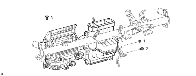
w/o Heater:
Install the air conditioning unit assembly onto the instrument panel reinforcement with the 2 bolts and nut in the order shown in the illustration.
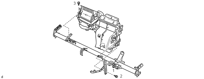
w/ Heater:
Install the air conditioning unit assembly onto the instrument panel reinforcement with the 2 bolts and nut in the order shown in the illustration.
87010
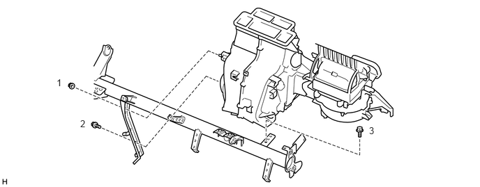
2.INSTALL AIR CONDITIONING UNIT ASSEMBLY (for LHD)
Install the air conditioning unit assembly onto the instrument panel reinforcement with the 2 bolts and nut in the order shown in the illustration.
55331
3.INSTALL INSTRUMENT PANEL REINFORCEMENT (for RHD)
Install the instrument panel reinforcement with the air conditioning unit assembly with the 5 bolts.
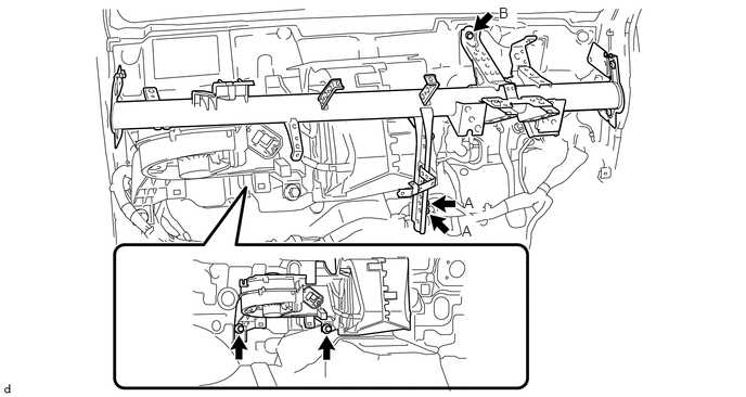
- Torque:
- Bolt A : 8.0 N*m (82 kgf*cm, 71 in.*lbf)
- Bolt B : 18.5 N*m (189 kgf*cm, 14 ft.*lbf)
Install the 4 bolts to the front pillar.
- Torque:
- 29 N*m (296 kgf*cm, 21 ft.*lbf)
Install the bolt in the engine compartment.
55331
4.INSTALL INSTRUMENT PANEL REINFORCEMENT (for LHD)
Install the instrument panel reinforcement with the air conditioning unit assembly with the 4 bolts.
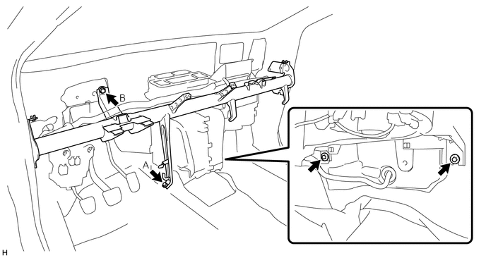
- Torque:
- Bolt A : 8.0 N*m (82 kgf*cm, 71 in.*lbf)
- Bolt B : 18.5 N*m (189 kgf*cm, 14 ft.*lbf)
Install the 4 bolts to the front pillar.
- Torque:
- 29 N*m (296 kgf*cm, 21 ft.*lbf)
Install the bolt in the engine compartment.
55352A
5.INSTALL NO. 2 INSTRUMENT PANEL TO FLOOR BRACE
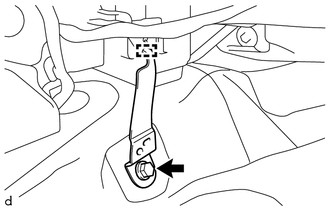
Engage the guide to install No. 2 instrument panel to floor brace with the bolt.
- Torque:
- 18.5 N*m (189 kgf*cm, 14 ft.*lbf)
- HINT:
-
Use the same procedure for the RHD and LHD vehicles.
88539J
6.INSTALL DRAIN COOLER HOSE
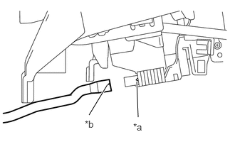
| *a | Rib |
| *b | Notched Section |
Install the drain cooler hose to the air conditioning unit assembly as shown in the illustration.
- HINT:
-
Align the notched section of the hose with the rib on the case.
Install the drain cooler hose and grommet with the bolt.
- Torque:
- 8.0 N*m (82 kgf*cm, 71 in.*lbf)
- HINT:
-
Use the same procedure for the RHD and LHD vehicles.
87220
7.INSTALL AIR DUCT ASSEMBLY
Install the air duct assembly with the 2 bolts.
- HINT:
-
Use the same procedure for the RHD and LHD vehicles.
82141
8.INSTALL INSTRUMENT PANEL WIRE (for RHD)
Engage the 2 claws to connect the DLC3 connector.
Install the instrument panel wire onto the instrument panel reinforcement with the 2 clamps.
Connect the ground wire onto the instrument panel reinforcement with the bolt.
Connect the ground wire onto the instrument panel reinforcement with the bolt and engage the 3 clamps.
Connect the connector and engage the clamp.
Connect the connector and engage the 4 clamps.
Connect the 2 connectors and engage the 2 clamps.
82141
9.INSTALL INSTRUMENT PANEL WIRE (for LHD)
Install the instrument panel wire onto the instrument panel reinforcement with the 4 clamps.
Connect the ground wire onto the instrument panel reinforcement with the 2 bolts.
Engage the 3 clamps.
Connect the ground wire onto the instrument panel reinforcement with the bolt.
Engage the 3 clamps.
Connect the connector and engage the and clamp.
Engage the 3 clamps.
Connect the ground wire onto the instrument panel reinforcement with the bolt.
Connect the 2 connectors and engage the clamp.
82600
10.INSTALL FUSE BLOCK ASSEMBLY
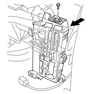
Install the fuse block assembly with the bolt as shown indicated by the arrow in the illustration.
- Torque:
- 5.0 N*m (51 kgf*cm, 44 in.*lbf)
Connect each connector.
82673B
11.INSTALL JUNCTION BLOCK BRACKET (for LHD)
Install the junction block bracket with the 2 bolts.
55453D
12.INSTALL NO. 1 INSTRUMENT PANEL SAFETY PAD
Engage the 2 clamps to install the No. 1 instrument panel safety pad.
- HINT:
-
Use the same procedure for the RHD and LHD vehicles.
55454B
13.INSTALL NO. 2 INSTRUMENT PANEL SAFETY PAD
- HINT:
-
Use the same procedure as for the No. 1 instrument panel safety pad.
55317
14.INSTALL INSTRUMENT PANEL PATCH
Install the instrument panel patch with the 2 bolts.
- Torque:
- 8.0 N*m (82 kgf*cm, 71 in.*lbf)
45250
15.INSTALL STEERING COLUMN ASSEMBLY
55312
16.INSTALL LOWER INSTRUMENT PANEL SUB-ASSEMBLY
55301
17.INSTALL INSTRUMENT PANEL SUB-ASSEMBLY
88716A
18.INSTALL COOLER REFRIGERANT LIQUID PIPE A (for RHD)
Remove the vinyl tape from the cooler refrigerant liquid pipe A and the connecting portion of the air conditioning unit assembly.
Apply sufficient compressor oil (ND-OIL8 or equivalent) to a new O-ring and the connecting part of the cooler refrigerant liquid pipe A.
- Compressor oil:
ND-OIL8 or equivalent
Install the O-ring onto the cooler refrigerant liquid pipe A.
Connect the cooler refrigerant liquid pipe A onto the air conditioning unit assembly.
88716A
19.INSTALL COOLER REFRIGERANT LIQUID PIPE A (for LHD)
Remove the vinyl tape from the cooler refrigerant liquid pipe A and the connecting portion of the air conditioning unit assembly.
Apply sufficient compressor oil (ND-OIL8 or equivalent) to a new O-ring and the connecting part of the cooler refrigerant liquid pipe A.
- Compressor oil:
ND-OIL8 or equivalent
Install the O-ring onto the cooler refrigerant liquid pipe A.
Connect the cooler refrigerant liquid pipe A onto the air conditioning unit assembly.
88712D
20.INSTALL SUCTION HOSE (for RHD)
Remove the vinyl tape from the suction hose and the connecting part of the air conditioning unit assembly.
Apply sufficient compressor oil (ND-OIL8 or equivalent) to a new O-ring and the connecting part of the suction hose.
- Compressor oil:
ND-OIL8 or equivalent
Install the O-ring onto the suction hose.
Connect the suction hose onto the air conditioning unit assembly.
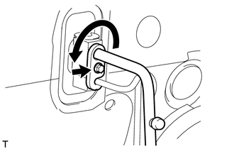
Turn the hook connector in the direction indicated by the arrow in the illustration.
Insert the pipe joints securely into the fitting holes and tighten the bolt.
- Torque:
- 6.2 N*m (63 kgf*cm, 55 in.*lbf)
88712D
21.INSTALL SUCTION HOSE (for LHD)
Remove the vinyl tape from the suction hose and the connecting part of the air conditioning unit assembly.
Apply sufficient compressor oil (ND-OIL8 or equivalent) to a new O-ring and the connecting part of the suction hose.
- Compressor oil:
ND-OIL8 or equivalent
Install the O-ring onto the suction hose.
Connect the suction hose onto the air conditioning unit assembly.
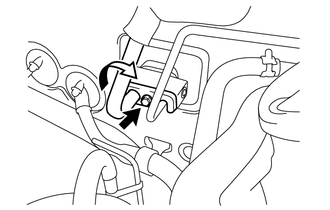
Turn the hook connector in the direction indicated by the arrow in the illustration.
Insert the pipe joints securely into the fitting holes and tighten the bolt.
- Torque:
- 6.2 N*m (63 kgf*cm, 55 in.*lbf)
88899P
22.INSTALL COVER PLATE (w/o Air Conditioning System)
Install the cover plate with the bolt.
- Torque:
- 6.2 N*m (63 kgf*cm, 55 in.*lbf)
87246X
23.INSTALL NO. 2 HEATER WATER HOSE (w/ Heater)
Connect the No. 2 heater water hose to the air conditioning unit with the clamp.
- HINT:
-
Use the same procedure for the RHD and LHD vehicles.
87245X
24.INSTALL NO. 1 HEATER WATER HOSE (w/ Heater)
Connect the No. 1 heater water hose to the air conditioning unit with the clamp.
- HINT:
-
Use the same procedure for the RHD and LHD vehicles.
25.CONNECT CABLE TO NEGATIVE BATTERY TERMINAL
- Torque:
- 6.4 N*m (65 kgf*cm, 57 in.*lbf)
26.ADD ENGINE COOLANT
for 1NR-VE (Click hereEngine / Hybrid System>1NR-VE COOLING>COOLANT>REPLACEMENT)
for 2NR-VE (Click hereEngine / Hybrid System>2NR-VE COOLING>COOLANT>REPLACEMENT)
27.CHARGE REFRIGERANT
28. WARM UP ENGINE
29.INSPECT FOR REFRIGERANT LEAK
30.INSPECT FOR COOLANT LEAK
for 1NR-VE (Click hereEngine / Hybrid System>1NR-VE COOLING>COOLING SYSTEM>ON-VEHICLE INSPECTION)
for 2NR-VE (Click hereEngine / Hybrid System>2NR-VE COOLING>COOLING SYSTEM>ON-VEHICLE INSPECTION)