2NR-VE ENGINE CONTROL SFI SYSTEM(w/o Air Fuel Ratio Sensor) VC Output Circuit
DESCRIPTION
The ECM constantly generates 5 V power source voltage from the battery voltage supplied to the +B1 (BAT) terminal to operate the microprocessor. The ECM also provides this power to the sensors through the VC output circuit.
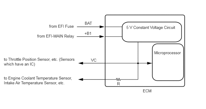
When the VC circuit is short-circuited, the sensors that are supplied with power through the VC circuit are deactivated because the power is not supplied from the VC circuit.
WIRING DIAGRAM
ECM Power Source Circuit
VC Output Circuit
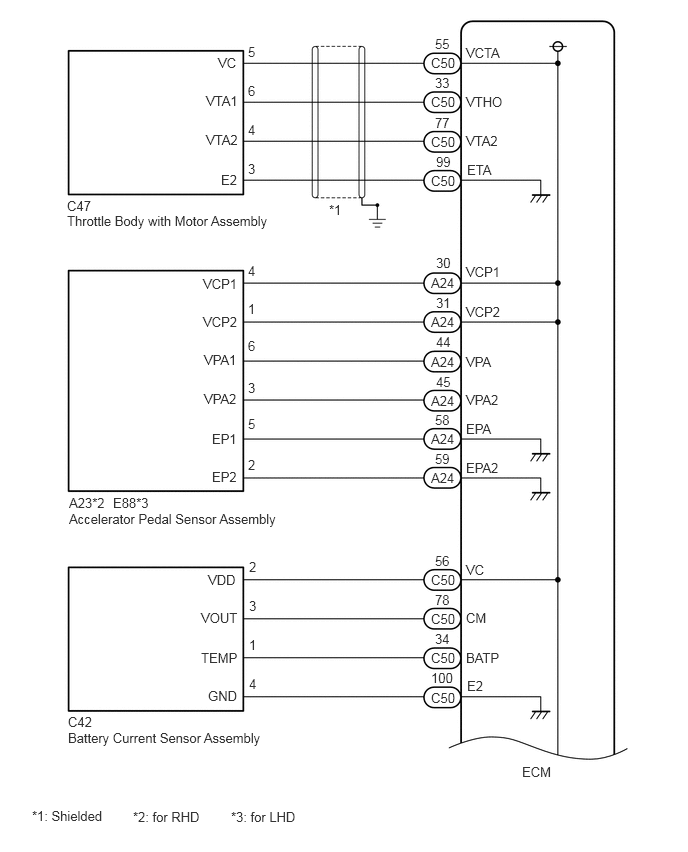
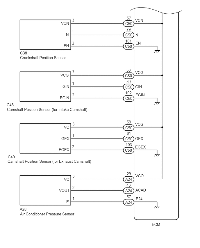
CAUTION / NOTICE / HINT
- NOTICE:
-
Inspect the fuses for circuits related to this system before performing the following procedure.
PROCEDURE
Connect the GTS to the DLC3.
Turn the ignition switch to ON.
Turn the GTS on.
Check the communication between the GTS and ECM.
- HINT:
-
Checking the Data List for "EFI" is possible.
- Result:
Result Proceed to Communication is not possible A Communication is possible B
A
B
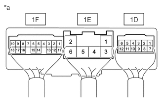
| *a | Component with harness connected
(No. 1 Integration Relay) |
Turn the ignition switch to ON.
Measure the voltage according to the value(s) in the table below.
- Standard Voltage:
Tester Connection Switch Condition Specified Condition 1F-10 - Body ground Ignition switch ON 11 to 14 V
- HINT:
- ·
Measure the voltage with the No. 1 integration relay connectors 1D, 1E and 1F connected.
·If the result is not as specified, the system may not be activated due to no power supply to the ECM terminals +B1 and +B2.
- Result:
Proceed to OK NG
OK
NG
Disconnect the throttle body with motor assembly connector.
Turn the ignition switch to ON.
Turn the GTS on.
Check the communication between the GTS and ECM.
- HINT:
-
Checking the Data List for "EFI" is possible.
- Result:
Result Proceed to Communication is not possible A Communication is possible B
A
B
Disconnect the accelerator pedal sensor assembly connector.
Turn the ignition switch to ON.
Turn the GTS on.
Check the communication between the GTS and ECM.
- HINT:
-
Checking the Data List for "EFI" is possible.
- Result:
Result Proceed to Communication is not possible A Communication is possible B
A
B
Disconnect the battery current sensor assembly connector.
Turn the ignition switch to ON.
Turn the GTS on.
Check the communication between the GTS and ECM.
- HINT:
-
Checking the Data List for "EFI" is possible.
- Result:
Result Proceed to Communication is not possible A Communication is possible B
A
B
Disconnect the crankshaft position sensor connector.
Turn the ignition switch to ON.
Turn the GTS on.
Check the communication between the GTS and ECM.
- HINT:
-
Checking the Data List for "EFI" is possible.
- Result:
Result Proceed to Communication is not possible A Communication is possible B
A
B
Disconnect the camshaft position sensor (for intake camshaft) connector.
Turn the ignition switch to ON.
Turn the GTS on.
Check the communication between the GTS and ECM.
- HINT:
-
Checking the Data List for "EFI" is possible.
- Result:
Result Proceed to Communication is not possible A Communication is possible B
A
B
Disconnect the camshaft position sensor (for exhaust camshaft) connector.
Turn the ignition switch to ON.
Turn the GTS on.
Check the communication between the GTS and ECM.
- HINT:
-
Checking the Data List for "EFI" is possible.
- Result:
Result Proceed to Communication is not possible A Communication is possible B
A
B
Disconnect the air conditioner pressure sensor connector.
Turn the ignition switch to ON.
Turn the GTS on.
Check the communication between the GTS and ECM.
- HINT:
-
Checking the Data List for "EFI" is possible.
- Result:
Result Proceed to Communication is not possible A Communication is possible B
A
B
Disconnect the throttle body with motor assembly connector.
Disconnect the accelerator pedal sensor assembly connector.
Disconnect the battery current sensor assembly connector.
Disconnect the crankshaft position sensor connector.
Disconnect the camshaft position sensor (for intake camshaft) connector.
Disconnect the camshaft position sensor (for exhaust camshaft) connector.
Disconnect the air conditioner pressure sensor connector.
Disconnect the ECM connectors.
Measure the resistance according to the value(s) in the table below.
- Standard Resistance:
Tester Connection Condition Specified Condition C50-55 (VCTA) - Body ground Always 10 kΩ or higher A24-30 (VCP1) - Body ground Always 10 kΩ or higher A24-31 (VCP2) - Body ground Always 10 kΩ or higher C50-56 (VC) - Body ground Always 10 kΩ or higher C50-57 (VCN) - Body ground Always 10 kΩ or higher C50-58 (VCG) - Body ground Always 10 kΩ or higher C50-59 (VCG) - Body ground Always 10 kΩ or higher A24-29 (VCO) - Body ground Always 10 kΩ or higher 1F-10 - A24-1 (+B1) Always Below 1 Ω 1F-10 - A24-2 (+B2) Always Below 1 Ω A24-1 (+B1) - Body ground Always 10 kΩ or higher A24-2 (+B2) - Body ground Always 10 kΩ or higher
- Result:
Proceed to OK NG
OK
NG