Home › Audio / Visual / Telematics › AUDIO / VIDEO › AUDIO AND VISUAL SYSTEM(for Radio Receiver Type) › from 2015.08
RM19Y0E _56 Audio / Visual / Telematics _003000 AUDIO / VIDEO _0015166 AUDIO AND VISUAL SYSTEM(for Radio Receiver Type) J

AUDIO / VIDEO  AUDIO AND VISUAL SYSTEM(for Radio Receiver Type)  Illumination Circuit  


DESCRIPTION

Power is supplied to the stereo component tuner assembly illumination when the light control switch is in the tail or head position.

WIRING DIAGRAM
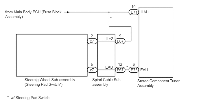
E232728E04
4.948,2.823 6.469,3.594 1.521,0.771 10 false Stereo Component Tuner Assembly 5.063,0.344 5.698,0.781 0.635,0.438 10 false ILM+ 4.708,0.354 5.302,0.719 0.594,0.365 10 false E71 4.708,2.427 5.271,2.719 0.563,0.292 10 false E73 4.208,1.396 4.688,1.719 0.479,0.323 10 false E67 3.24,1.396 3.646,1.667 0.406,0.271 10 false z7 3.24,2.427 3.667,2.719 0.427,0.292 10 false z7 4.208,2.427 4.646,2.813 0.438,0.385 10 false E67 4.729,0.156 5.073,0.49 0.344,0.333 10 false 10 3.969,0.563 4.323,0.854 0.354,0.292 10 false * 4.552,2.344 4.74,2.51 0.188,0.167 10 false * 0.188,0.344 2.302,1.167 2.115,0.823 10 false from Main Body ECU (Fuse Block Assembly) 0.885,2.781 2.813,3.438 1.927,0.656 10 false Steernig Wheel Sub-assembly (Steering Pad Switch*) 0.26,3.427 2.188,3.802 1.927,0.375 10 false *: w/ Steering Pad Switch 3.323,2.781 4.448,3.656 1.125,0.875 10 false Spiral Cable Sub-assembly 3.792,2.333 4.313,2.615 0.521,0.281 10 false EAU 4.781,2.229 5.115,2.573 0.333,0.344 10 false 6 4.25,2.229 4.583,2.563 0.333,0.333 10 false 12 3.271,2.229 3.573,2.531 0.302,0.302 10 false 5 3.802,1.302 4.271,1.573 0.469,0.271 10 false IL+2 4.292,1.208 4.604,1.51 0.313,0.302 10 false 9 3.271,1.208 3.594,1.531 0.323,0.323 10 false 2 5.052,2.427 5.677,2.76 0.625,0.333 10 false EAU

PROCEDURE

1.CHECK ILLUMINATION
a.

Check if the illumination for the stereo component tuner assembly, heater control switch or others (hazard switch, transmission control switch, etc.) comes on when the light control switch is turned to the head or tail position.

Result:
Result Proceed to
Illumination comes on for all components except stereo component tuner assembly. A
Illumination comes on for all components except steering wheel sub-assembly (steering pad switch). B
No illumination comes on (stereo component tuner assembly, hazard switch, etc.). C


A

2.CHECK HARNESS AND CONNECTOR (POWER SOURCE - STEREO COMPONENT TUNER ASSEMBLY)

B

3.INSPECT STEERING WHEEL SUB-ASSEMBLY (STEERING PAD SWITCH)

C

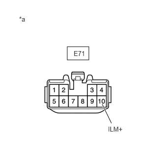
2.CHECK HARNESS AND CONNECTOR (POWER SOURCE - STEREO COMPONENT TUNER ASSEMBLY)
a.
E230878C05
1.427,0.99 1.885,1.271 0.458,0.281 2.167,2.208 2.365,2.615 true 2.292,2.656 2.625,2.833 0.333,0.177 10 false ILM+ 1.563,1.052 2.115,1.365 0.552,0.313 10 false E71 0.406,0.323 0.917,0.76 0.51,0.438 10 false *a
*a Front view of wire harness connector
(to Stereo Component Tuner Assembly)


Disconnect the E71 stereo component tuner assembly connector.


b.

Measure the voltage according to the value(s) in the table below.

Standard Voltage:
Tester Connection Switch Condition Specified Condition
E71-10 (ILM+) - Body ground Light control switch tail or head 11 to 14 V


Result:
Proceed to
OK
NG


OK

NG

REPAIR OR REPLACE HARNESS OR CONNECTOR

3.INSPECT STEERING WHEEL SUB-ASSEMBLY (STEERING PAD SWITCH)
a.

Remove the steering wheel sub-assembly (steering pad switch).

Click hereSteering>STEERING COLUMN>STEERING WHEEL>REMOVAL


b.

Inspect the steering wheel sub-assembly (steering pad switch).

Click hereSteering>STEERING COLUMN>STEERING WHEEL>INSPECTION

Result:
Proceed to
OK
NG


OK

4.INSPECT SPIRAL CABLE SUB-ASSEMBLY

NG

REPLACE STEERING WHEEL SUB-ASSEMBLY

4.INSPECT SPIRAL CABLE SUB-ASSEMBLY
a.

Remove the spiral cable sub-assembly.

Click hereVehicle Interior>SUPPLEMENTAL RESTRAINT SYSTEMS>SPIRAL CABLE>REMOVAL


b.

Inspect the spiral cable sub-assembly.

Click hereVehicle Interior>SUPPLEMENTAL RESTRAINT SYSTEMS>SPIRAL CABLE>INSPECTION

Result:
Proceed to
OK
NG


OK

5.CHECK HARNESS AND CONNECTOR (SPIRAL CABLE SUB-ASSEMBLY - STEREO COMPONENT TUNER ASSEMBLY)

NG

REPLACE SPIRAL CABLE SUB-ASSEMBLY

5.CHECK HARNESS AND CONNECTOR (SPIRAL CABLE SUB-ASSEMBLY - STEREO COMPONENT TUNER ASSEMBLY)
a.

Disconnect the E67 spiral cable sub-assembly connector.


b.

Disconnect the E73 stereo component tuner assembly connector.


c.

Measure the resistance according to the value(s) in the table below.

Standard Resistance (Check for Open):
Tester Connection Switch Condition Specified Condition
E67-12 (EAU) - E73-6 (EAU) Always Below 1 Ω


Standard Resistance (Check for Short):
Tester Connection Switch Condition Specified Condition
E67-12 (EAU) or E73-6 (EAU) - Body ground Always 10 kΩ or higher


Result:
Proceed to
OK
NG


OK

REPAIR OR REPLACE HARNESS OR CONNECTOR (SPIRAL CABLE -POWER SOURCE)

NG

REPAIR OR REPLACE HARNESS OR CONNECTOR