A4R AUTOMATIC TRANSMISSION / TRANSAXLE AUTOMATIC TRANSMISSION SYSTEM P0562 System Voltage Low
DESCRIPTION
Battery power source (+B1, +B2) is cut off for a specific period of time.
| DTC No. | Detection Item | DTC Detection Condition | Trouble Area | MIL | Warning Indicate | Memory | Note |
|---|---|---|---|---|---|---|---|
| P0562 | System Voltage Low | 1. Diagnosis Condition 2. Malfunction Status 3. Malfunction Time 4. Other
1.
Ignition switch ON 2.
Battery power source (+B1, +B2) is cut off for a specific period of time. 3.
0.1 seconds 4.
1-trip detection logic |
·
No. 1 integration relay ·
Open or short in battery power source circuit ·
ECM |
Comes on | Blinks | DTC stored | - |
MIL:"Comes on" means the MIL (Malfunction Indicator Light) illuminates.
Memory:"DTC stored" means the ECM stores the trouble code if the ECU detects the DTC detection condition.
WIRING DIAGRAM
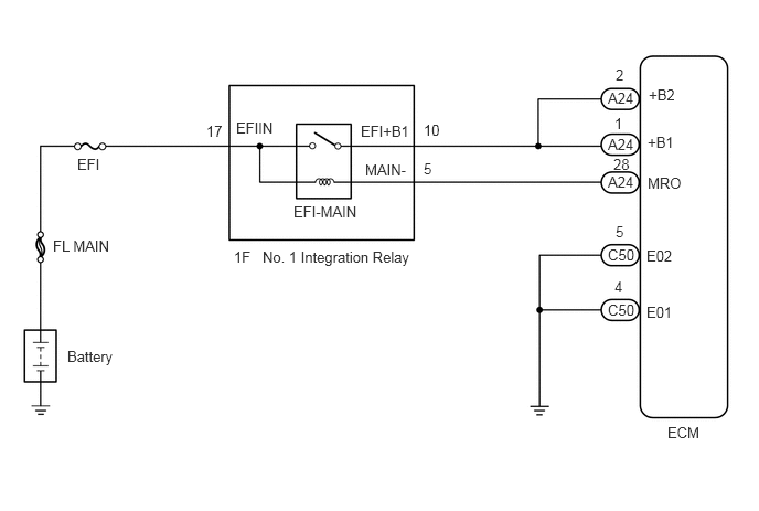
CAUTION / NOTICE / HINT
- NOTICE:
-
Inspect the fuses for circuits related to this system before performing the following procedure.
PROCEDURE
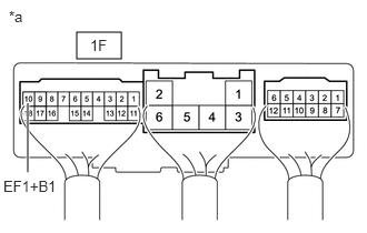
| *a | Component with harness connected
(No. 1 Integration Relay) |
Turn the ignition switch to ON.
Measure the voltage according to the value(s) in the table below.
- Standard Voltage:
Tester Connection Switch Condition Specified Condition 1F-10 (EF1+B1) - Body ground Ignition switch ON 11 to 14 V
- Result:
Proceed to OK NG
OK
NG
Disconnect the 1F No. 1 integration relay connector.
Disconnect the A24 ECM connector.
Measure the resistance according to the value(s) in the table below.
- Standard Resistance (Check for open):
Tester Connections Condition Specified Conditions A24-1 (+B1) - 1F-10 (EFI+B1) Always Below 1 Ω A24-2 (+B2) - 1F-10 (EFI+B1) Always Below 1 Ω A24-28 (MR0) - 1F-5 (MAIN-) Always Below 1 Ω
- Standard Resistance (Check for short):
Tester Connections Condition Specified Conditions A24-1 (+B1) or 1F-10 (EFI+B1) - Body ground Always 10 kΩ or higher A24-2 (+B2) or 1F-10 (EFI+B1) - Body ground Always 10 kΩ or higher A24-28 (MR0) or 1F-5 (MAIN-) - Body ground Always 10 kΩ or higher
Reconnect the A24 ECM connector.
Reconnect the 1F No. 1 integration relay connector.
- Result:
Result Proceed to OK (for 1NR-VE) A OK (for 2NR-VE) B NG C
A
B
C
Disconnect the C50 ECM connector.
Measure the resistance according to the value(s) in the table below.
- Standard Resistance:
Tester Connection Condition Specified Condition C50-4 (E01) - Body ground Always Below 1 Ω C50-5 (E02) - Body ground Always Below 1 Ω
Reconnect the C50 ECM connector.
- Result:
Proceed to OK NG
OK
NG
Check the No. 1 integration relay (EFI-MAIN relay).
for 1NR-VE: Click hereEngine / Hybrid System>1NR-VE ENGINE CONTROL>INTEGRATION RELAY>INSPECTION
for 2NR-VE: Click hereEngine / Hybrid System>2NR-VE ENGINE CONTROL>INTEGRATION RELAY>INSPECTION
- Result:
Result Proceed to OK A NG (for 1NR-VE) B NG (for 2NR-VE) C
A
B
C
Disconnect the negative battery terminal.
Disconnect the positive battery terminal.
Measure the resistance according to the value(s) in the table below.
- Standard Resistance (Check for open):
Tester Connections Condition Specified Conditions Positive battery terminal - 1F-17 (EFIIN) Always Below 1 Ω
- Standard Resistance (Check for short):
Tester Connections Condition Specified Conditions 1F-17 (EFIIN) - Body ground Always 10 kΩ or higher
Reconnect the positive battery terminal.
Reconnect the negative battery terminal.
- Result:
Proceed to OK NG
OK
NG