M20A-FXS HYBRID / BATTERY CONTROL FUSE BOX REMOVAL
CAUTION / NOTICE / HINT
The necessary procedures (adjustment, calibration, initialization or registration) that must be performed after parts are removed and installed, or replaced during hybrid battery terminal block removal/installation are shown below.
| Replaced Part or Performed Procedure | Necessary Procedures | Effect/Inoperative Function when Necessary Procedure not Performed | Link |
|---|---|---|---|
|
*1: When performing learning using the GTS. Click here( |
|||
| Disconnect cable from negative auxiliary battery terminal | Perform steering sensor zero point calibration | Lane departure alert system (w/ Steering Control) | ( ) |
| Toyota parking assist-sensor system*1 | |||
| Parking support brake system*1 | |||
| Simple intelligent parking assist system*1 | |||
| Pre-collision System | |||
| Memorize steering angle neutral point | Panoramic view monitor system | ()
|
|
| Initialize back door lock | Power Door Lock Control System | ()
|
|
| Replacement of hybrid battery terminal block | Perform high voltage fuse accumulated load history reset | DTCs are stored | ()
|
- CAUTION:
- ·
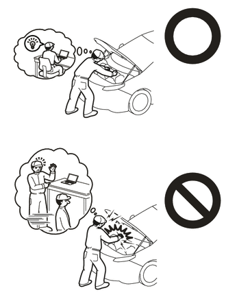
Orange wire harnesses and connectors indicate high-voltage circuits. To prevent electric shock, always follow the procedure described in the repair manual.
Click hereEngine / Hybrid System>M20A-FXS (HYBRID / BATTERY CONTROL)>HYBRID CONTROL SYSTEM>PRECAUTION
·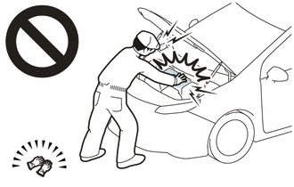
Be sure to wear insulating gloves when working on high voltage wiring or components.
·If work is performed without wearing insulating gloves, there is a danger of electric shock.
PROCEDURE

 1. PRECAUTION
- NOTICE:
-
After turning the power switch off, waiting time may be required before disconnecting the cable from the negative (-) auxiliary battery terminal. Therefore, make sure to read the disconnecting the cable from the negative (-) auxiliary battery terminal notices before proceeding with work.
-
Click hereGeneral>INTRODUCTION>REPAIR INSTRUCTION>PRECAUTION
G3834
2.REMOVE SERVICE PLUG GRIP
82121
3.DISCONNECT ENGINE WIRE
4.REMOVE CONNECTOR COVER ASSEMBLY
5.CHECK TERMINAL VOLTAGE
6.INSTALL CONNECTOR COVER ASSEMBLY
82121
7.CONNECT ENGINE WIRE
73350C
8.DISCONNECT REAR CENTER SEAT OUTER BELT ASSEMBLY
9.REMOVE BENCH TYPE REAR SEAT CUSHION ASSEMBLY
72693
10.REMOVE REAR SEAT CUSHION LOCK HOOK
67918A
11.REMOVE REAR DOOR SCUFF PLATE LH
76974F
12.REMOVE REAR UNDER SIDE COVER LH
67917A
13.REMOVE REAR DOOR SCUFF PLATE RH
- HINT:
-
Use the same procedure as for the LH side.
76973F
14.REMOVE REAR UNDER SIDE COVER RH
- HINT:
-
Use the same procedure as for the LH side.
76971G
15.REMOVE REAR UNDER COVER
71033
16.REMOVE REAR SEAT CUSHION LEG SUB-ASSEMBLY
G9230
17.REMOVE BATTERY COOLING BLOWER ASSEMBLY
G92N4A
18.REMOVE NO. 1 HV BATTERY COVER PANEL RH
821H1
19.DISCONNECT HV FLOOR UNDER WIRE
82161
20.DISCONNECT FLOOR WIRE
G92PC
21.REMOVE NO. 1 HV BATTERY PROTECTOR
82161
22.DISCONNECT FLOOR WIRE
G920L
23.REMOVE UPPER NO. 1 HYBRID BATTERY COVER SUB-ASSEMBLY
G92Q1
24.REMOVE NO. 1 HV BATTERY SHIELD PANEL
G92Z2
25.REMOVE HYBRID BATTERY TERMINAL BLOCK
- CAUTION:
-
Be sure to wear insulated gloves and protective goggles.
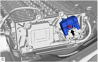
Remove the bolt.
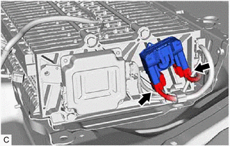
Disconnect the 2 hybrid battery terminal block connectors to remove the hybrid battery terminal block from the HV battery.
- NOTICE:
-
Insulate the disconnected high-voltage connectors with insulating tape.