2ZR-FXE EMISSION CONTROL EGR VALVE REMOVAL
CAUTION / NOTICE / HINT
The necessary procedures (adjustment, calibration, initialization or registration) that must be performed after parts are removed and installed, or replaced during EGR valve assembly removal/installation are shown below.
| Replaced Part or Performed Procedure | Necessary Procedures | Effect/Inoperative Function when Necessary Procedure not Performed | Link |
|---|---|---|---|
| Disconnect cable from negative auxiliary battery terminal | Memorize steering angle neutral point | Panoramic view monitor system | ( ) |
| Replacement of EGR valve assembly | Inspection After Repair | ·
Poor idle, etc. ·
Engine start function, etc. |
()
|
- CAUTION:
- ·
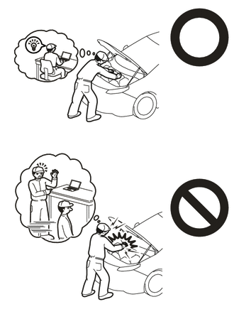
Orange wire harnesses and connectors indicate high-voltage circuits. To prevent electric shock, always follow the procedure described in the repair manual.
for NICKEL METAL HYDRIDE BATTERY:
for LITHIUM-ION BATTERY:
·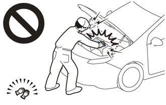
To prevent electric shock, wear insulated gloves when working on wire harnesses and components of the high voltage system.
- HINT:
-
When the cable is disconnected / reconnected to the battery terminal, systems temporarily stop operating. However, each system has a function that completes learning the first time the system is used.
- ·
Learning completes when vehicle is driven
Effect/Inoperative Function When Necessary Procedures are not Performed Necessary Procedures Link *1: When performing learning using the GTS
Click here(
)
Lane tracing assist system Drive the vehicle straight ahead at 35 km/h (22 mph) or more for 5 second or more. ( )
Pre-collision system Simple intelligent parking assist system*1 Parking support brake system*1 Toyota parking assist-sensor system*1
·Learning completes when vehicle is operated normally
Effect/Inoperative Function When Necessary Procedures are not Performed Necessary Procedures Link Power door lock control system
·Back door opener
Perform door unlock operation with door control switch or electrical key transmitter sub-assembly switch. ( )
Air conditioning system After the ignition switch is turned to ON, the servo motor standard position is recognized. -
PROCEDURE

 1. PRECAUTION
- NOTICE:
-
After turning the power switch off, waiting time may be required before disconnecting the cable from the negative (-) auxiliary battery terminal.
-
Click hereGeneral>INTRODUCTION>REPAIR INSTRUCTION>PRECAUTION
82121
2.DISCONNECT ENGINE WIRE
3.REMOVE AUXILIARY BATTERY
G3834
4.REMOVE SERVICE PLUG GRIP
5.REMOVE WINDSHIELD WIPER MOTOR AND LINK ASSEMBLY
55737B
6.REMOVE NO. 1 HEATER AIR DUCT SPLASH SHIELD SEAL
55735A
7.REMOVE WATER GUARD PLATE LH (for TMC Made RHD)
55736D
8.REMOVE COWL BODY MOUNTING REINFORCEMENT LH
55735C
9.REMOVE COWL BODY MOUNTING REINFORCEMENT RH
55701J
10.REMOVE OUTER COWL TOP PANEL SUB-ASSEMBLY (for LHD)
55701J
11.REMOVE OUTER COWL TOP PANEL SUB-ASSEMBLY (for RHD)
51441
12.REMOVE NO. 1 ENGINE UNDER COVER
13.DRAIN ENGINE COOLANT (for Engine)
89661
14.REMOVE ECM
74404A
15.REMOVE BATTERY CLAMP SUB-ASSEMBLY
33820B
16.SEPARATE TRANSMISSION CONTROL CABLE ASSEMBLY
82121
17.DISCONNECT ENGINE WIRE
18.REMOVE CONNECTOR COVER ASSEMBLY
19.CHECK TERMINAL VOLTAGE
20.TEMPORARILY INSTALL CONNECTOR COVER ASSEMBLY
821H1
21.DISCONNECT HV FLOOR UNDER WIRE
821H2
22.DISCONNECT HV AIR CONDITIONING WIRE
G9200
23.SEPARATE INVERTER WITH CONVERTER ASSEMBLY
- CAUTION:
-
Wear insulated gloves.
Remove the 5 bolts and 2 nuts and separate the inverter with converter assembly.
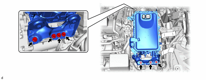
- NOTICE:
- ·
To prevent damage due to static electricity, do not touch the terminals of the inverter with converter assembly connector.
·Make sure to seal the inverter with converter assembly with the connector cover assembly or tape (non-residue type) etc., to prevent entry of foreign matter and water.
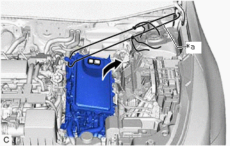
| *a | Rope |
Using a rope or equivalent, secure the inverter with converter assembly with the hood hinge.
- NOTICE:
- ·
Be careful not to damage the surrounding components when securing the inverter with converter assembly.
·To prevent damage to the inverter with converter assembly, do not hold the coolant pipe, bracket or connector when securing the inverter with converter assembly.
·To prevent damage due to static electricity, do not touch the terminals of the inverter with converter assembly connector.
·Make sure to seal the inverter with converter assembly with the connector cover assembly or tape (non-residue type) etc., to prevent entry of foreign matter and water.
25610
24.REMOVE EGR PIPE ASSEMBLY
25620
25.REMOVE EGR VALVE ASSEMBLY
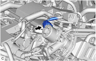
Disconnect the EGR valve assembly connector.
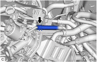
Slide the clip and disconnect the No. 6 water by-pass hose from the EGR valve assembly.
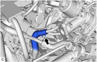
Slide the clip and disconnect the water by-pass hose from the EGR valve assembly.
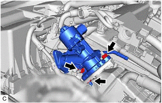
Remove the 3 nuts.
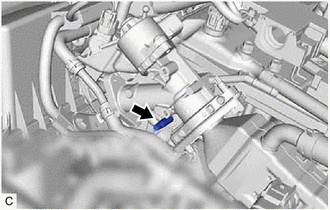
Using an E8 "TORX" socket wrench, remove the stud bolt from the camshaft housing sub-assembly.
- HINT:
-
If a stud bolt is deformed or the threads are damaged, replace it.
Remove the EGR valve assembly from the EGR pipe with cooler sub-assembly.
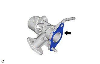
Remove the EGR valve gasket from the EGR valve assembly.