Fuel Injector
Fuel
COMPONENTS
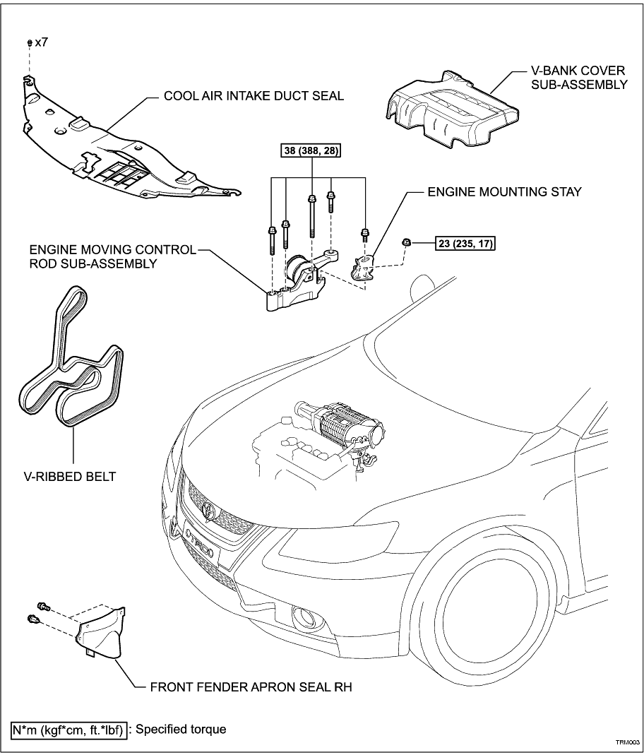
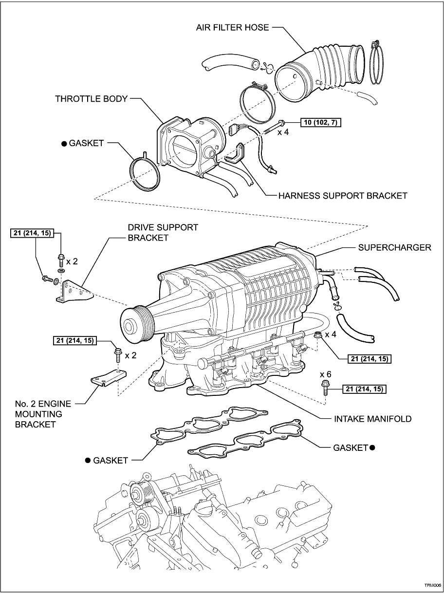
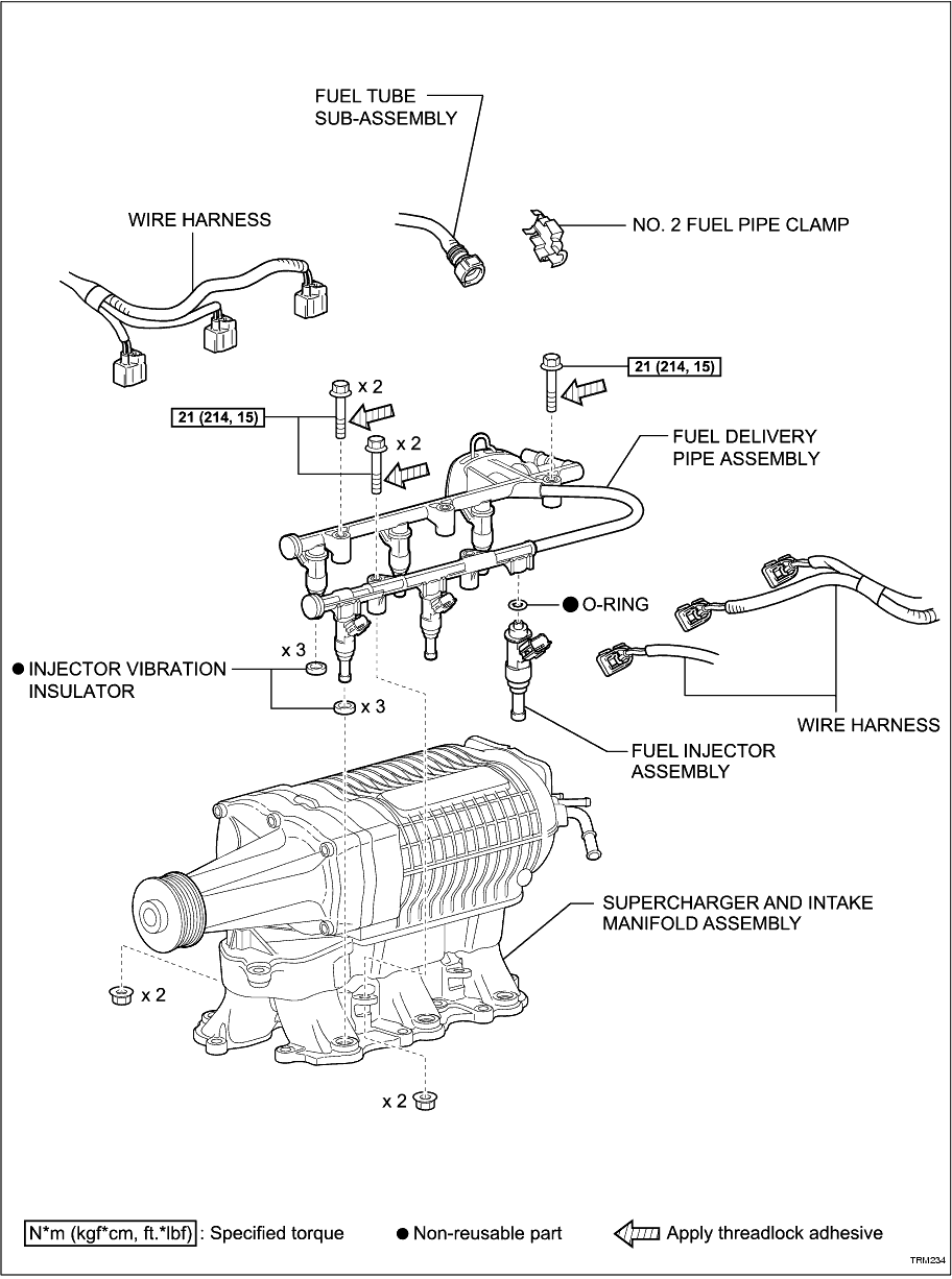
REMOVAL
1. DISCHARGE FUEL SYSTEM PRESSURE (
Click Here
)
2. DISCONNECT CABLE FROM BATTERY NEGATIVE TERMINAL
3. REMOVE COOL AIR INTAKE DUCT SEAL (
Click Here
)
4. REMOVE V-BANK COVER SUB-ASSEMBLY (
Click Here
)
5. REMOVE FRONT FENDER APRON SEAL RH
6. REMOVE ENGINE MOUNTING STAY (
Click Here
)
7. REMOVE ENGINE MOVING CONTROL ROD SUB-ASSEMBLY (
Click Here
)
8. REMOVE V-RIBBED BELT (
Click Here
)
9. REMOVE AIR FILTER HOSE (
Click Here
)
10. REMOVE DRIVE SUPPORT BRACKET (
Click Here
)
11. REMOVE NO. 2 ENGINE MOUNTING BRACKET (
Click Here
)
12. DISCONNECT VACUUM HOSES (
Click Here
)
13. SEPARATE THROTTLE BODY (
Click Here
)
14. DISCONNECT FUEL TUBE SUB-ASSEMBLY (
Click Here
)
15. REMOVE SUPERCHARGER AND INTAKE MANIFOLD ASSEMBLY (
Click Here
)
16. REMOVE FUEL DELIVERY PIPE ASSEMBLY
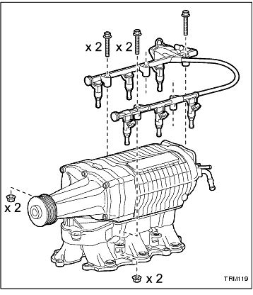
(a) Remove the front fuel delivery pipe assembly.
(1) Remove the 2 bolts and nuts and remove the fuel delivery pipe assembly and move to the side.
-
(b) Remove the rear fuel delivery pipe assembly.
(1) Remove the bolt from the inlet end of the fuel delivery pipe assembly.
(2) Remove the 2 bolts and nuts and completely remove the fuel delivery pipe assembly.
-
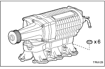
(c) Remove the 6 fuel injector vibration insulators from the intake manifold.
-
17. REMOVE FUEL INJECTORS
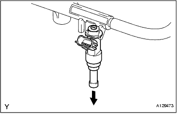
(a) Pull out the fuel injectors from the fuel delivery pipe.
-
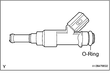
(b) Remove the 6 O-rings from the injectors.
-
INSPECTION
1. INSPECT FUEL INJECTOR ASSEMBLY
(a) Inspect injector resistance.
(1) Using an ohmmeter, measure the resistance between the terminals.
Resistance:
11.6 to 12.4 ohms at 20˚C (68˚F)
If the resistance is not as specified, replace the injector.
-
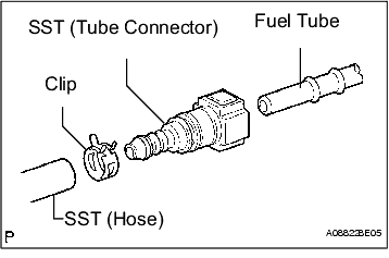
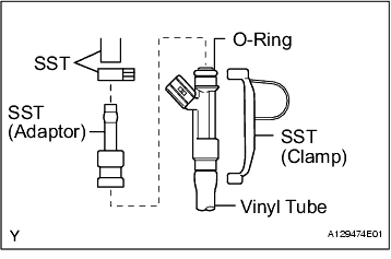
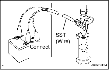
(b) Inspect the injection volume.
CAUTION:
This test involves high-pressure fuel and electricity. Take every precaution regarding safe handling of both the fuel and the electricity. Perform this test in a safe area, and avoid any sparks or flames. Do not smoke.
(1) Install the fuel tube connector to SST (hose), then connect the tube connector to the fuel pipe (vehicle side).
SST
09268-31011
(09268-41500
90467-13001
95336-08070)
(2) Install the O-ring to the fuel injector.
(3) Connect SST (adaptor and hose) to the injector, and hold the injector and union with SST (clamp).
SST
09268-31011
(90467-13001
95336-08070)
09268-41140
09268-41400
(4) Put the injector into the graduated cylinder.
CAUTION:
Install a suitable vinyl tube onto the injector to contain fuel spray.
(5) Operate the fuel pump. (
Click Here
)
(6) Connect SST (wire) to the injector and the battery for 15 seconds, and measure the injection volume with the graduated cylinder. Test each injector 2 or 3 times.
SST
09842-30080
Volume:
111 to 137 cm3 (6.7 to 8.3 cu in.) in 15 seconds
Difference between each injector:
16 cm3 (0.98 cu in.) or less
If the injection volume is not as specified, replace the injector.
-
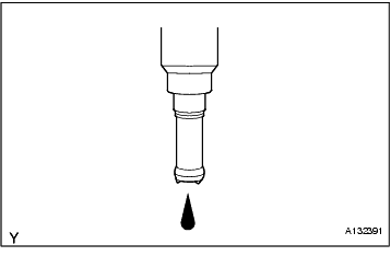
(c) Check the fuel leakage.
(1) In the condition above, disconnect the tester probes of SST (wire) from the battery and check the fuel leakage from the injector.
Fuel drop:
1 drop or less in 16 minutes
-
INSTALLATION
1. INSTALL FUEL INJECTORS
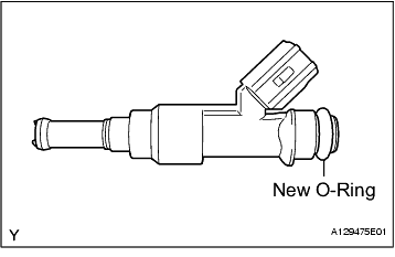
(a) Apply a light coat of spindle oil or gasoline to new O-rings, and install them to each injector.
-
(b) Apply a light coat of spindle oil or gasoline where the fuel delivery pipe contacts the O-ring.
-
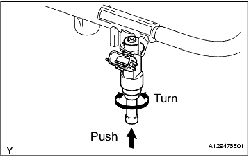
(c) Push the fuel injector while turning it to install the injector in the fuel delivery pipe.
-
(d) Position the fuel injector connector outward.
NOTICE:
• Be careful not to twist the O-ring.
• After installing the fuel injector, check it turns smoothly. If not, reinstall it with a new O-ring.
-
2. INSTALL FUEL DELIVERY PIPE ASSEMBLY
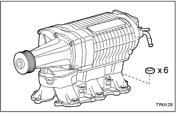
(a) Install 6 new fuel injector vibration insulators.
-
(b) Install the rear fuel delivery pipe assembly.
(1) Apply threadlock adhesive to the 3 bolts.
Adhesive:
Loctite 243 or equivalent
(2) Temporarily install the fuel delivery pipe assembly with 2 bolts and nuts.
(3) Temporarily install the bolt at the inlet end of the fuel delivery pipe assembly.
NOTICE:
After installing the fuel delivery pipe, check the injectors turn smoothly. If not, reinstall it with a new O-ring.
(4) Tighten the 3 bolts.
Torque:
21 N*m
(214 kgf*cm,
15 ft.*lbf)
-
(c) Install the front fuel delivery pipe assembly.
(1) Apply threadlock adhesive to the 2 bolts.
Adhesive:
Loctite 243 or equivalent
(2) Temporarily install the fuel delivery pipe assembly with the 2 bolts and nuts.
NOTICE:
After installing the fuel delivery pipe, check the injectors turn smoothly. If not, reinstall it with a new O-ring.
(3) Tighten the 2 bolts.
Torque:
21 N*m
(214 kgf*cm,
15 ft.*lbf)
-
3. INSTALL SUPERCHARGER AND INTAKE MANIFOLD ASSEMBLY (
Click Here
)
4. CONNECT FUEL TUBE SUB-ASSEMBLY (
Click Here
)
5. INSTALL THROTTLE BODY (
Click Here
)
6. CONNECT VACUUM HOSES (
Click Here
)
7. INSTALL NO. 2 ENGINE MOUNTING BRACKET (
Click Here
)
8. INSTALL DRIVE SUPPORT BRACKET (
Click Here
)
9. INSTALL AIR FILTER HOSE (
Click Here
)
10. INSTALL V-RIBBED BELT (
Click Here
)
11. INSTALL ENGINE MOVING CONTROL ROD SUB-ASSEMBLY (
Click Here
)
12. INSTALL ENGINE MOUNTING STAY (
Click Here
)
13. INSTALL FRONT FENDER APRON SEAL RH
14. CONNECT CABLE TO BATTERY NEGATIVE TERMINAL
15. INSPECT ENGINE IDLE SPEED (
Click Here
)
16. INSTALL V-BANK COVER SUB-ASSEMBLY (
Click Here
)
17. INSTALL COOL AIR INTAKE DUCT SEAL (
Click Here
)