Supercharger Assembly
Supercharger
COMPONENTS
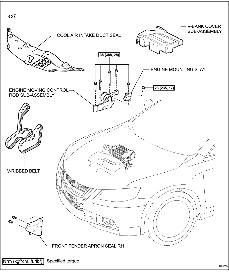
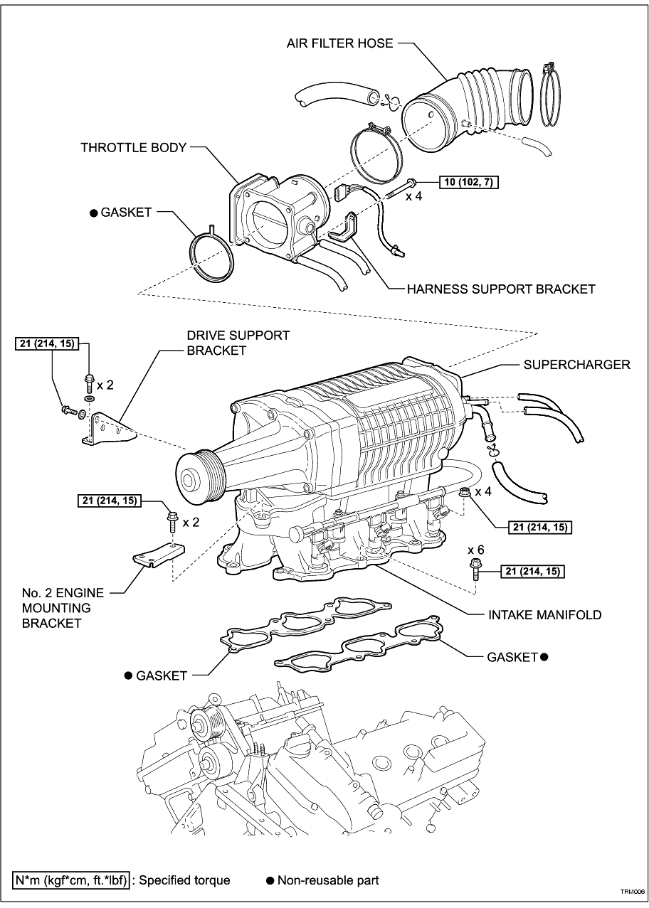
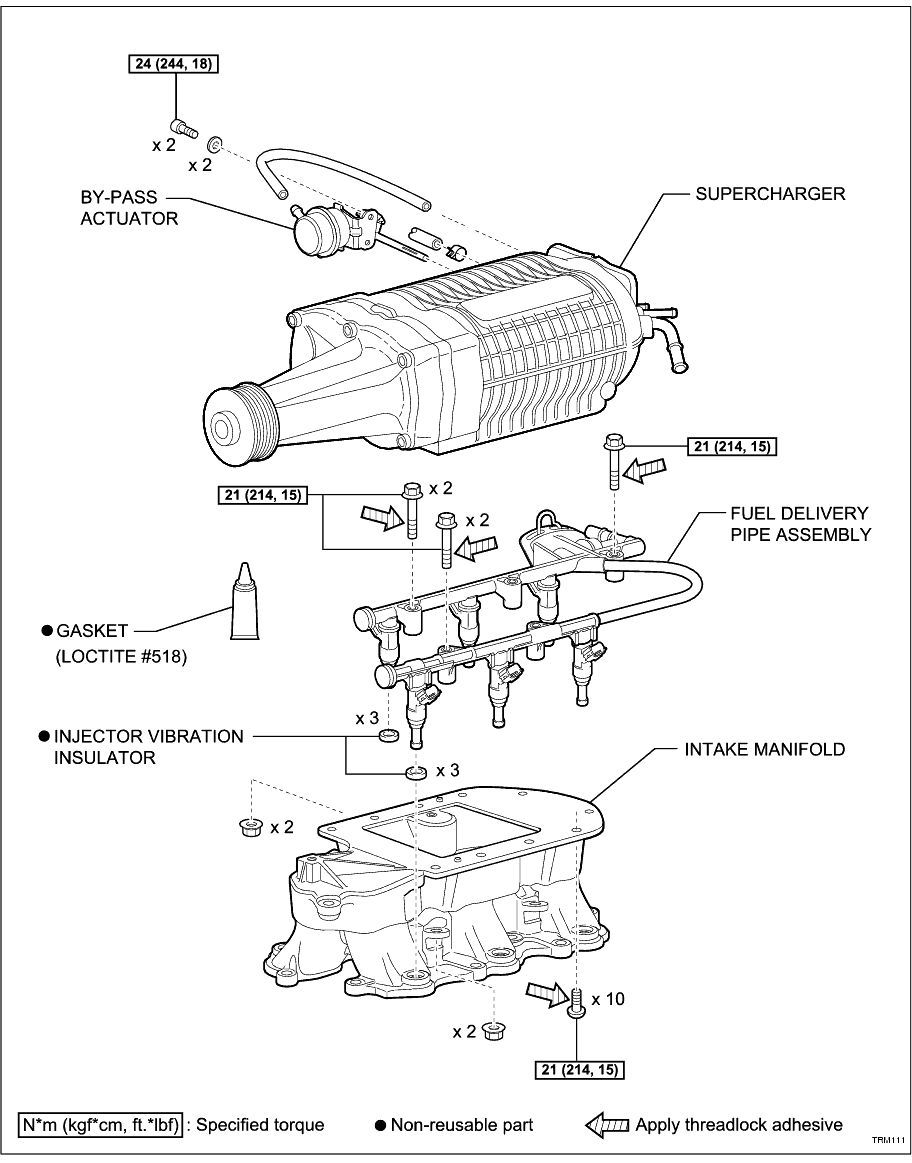
REMOVAL
1. DISCHARGE FUEL SYSTEM PRESSURE (
Click Here
)
2. DISCONNECT CABLE FROM BATTERY NEGATIVE TERMINAL
3. REMOVE COOL AIR INTAKE DUCT SEAL (
Click Here
)
4. REMOVE V-BANK COVER SUB-ASSEMBLY (
Click Here
)
5. REMOVE FRONT FENDER APRON SEAL RH
6. REMOVE ENGINE MOUNTING STAY (
Click Here
)
7. REMOVE ENGINE MOVING CONTROL ROD SUB-ASSEMBLY (
Click Here
)
8. REMOVE V-RIBBED BELT (
Click Here
)
9. REMOVE AIR FILTER HOSE
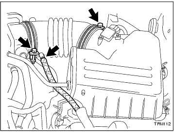
(a) Disconnect the ventilation hoses.
-
(b) Disconnect the hose bands and remove the air filter hose.
-
10. REMOVE DRIVE SUPPORT BRACKET
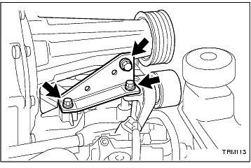
(a) Remove the 3 bolts and the drive support bracket.
-
11. REMOVE NO. 2 ENGINE MOUNTING BRACKET
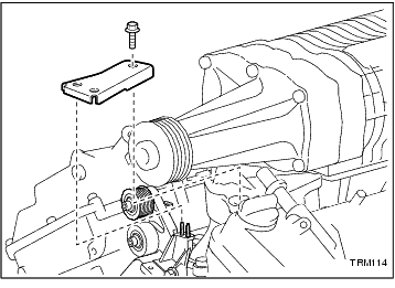
(a) Remove the bolt and the No. 2 engine mounting bracket.
-
12. DISCONNECT VACUUM HOSES
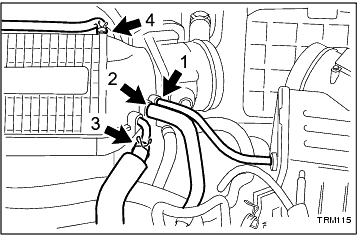
(a) Disconnect the air cleaner cap vacuum hose (1).
-
(b) Disconnect the vacuum switching valve hose (2).
-
(c) Disconnect the ventilation valve hose (3).
-
(d) Disconnect the brake booster vacuum hose (4).
-
13. SEPARATE THROTTLE BODY
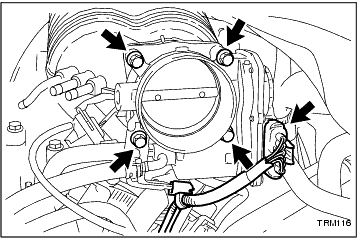
(a) Disconnect the wire connector.
-
(b) Remove the 4 bolts and separate the throttle body from the supercharger and remove the gasket.
HINT:
To avoid draining the cooling system, do not remove the coolant hoses. Place the throttle body to the side.
-
14. DISCONNECT FUEL TUBE SUB-ASSEMBLY
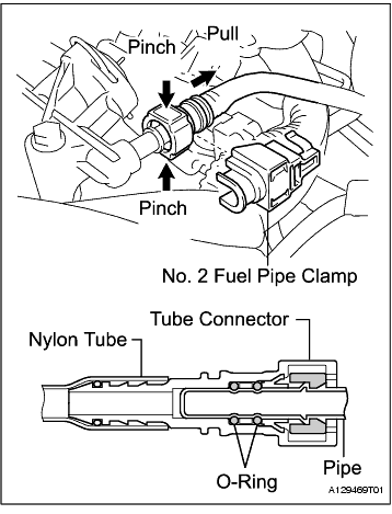
(a) Remove the No. 2 fuel pipe clamp.
-
(b) Pinch the tube connector and then pull out the fuel pipe.
NOTICE:
• Check there is no dirt or other foreign objects around the connector before this operation and clean the connector as necessary.
• Prevent mud or dirt from entering the quick connector. If mud enters the connector, the O-rings may not seal properly.
• Remove the quick connector by hand.
• Do not bend, kink, or twist the nylon tube. Protect the connector by covering it with a plastic bag.
• If the pipe and the connector are stuck, try wiggling or pushing and pulling the connector to release it and pull the connector out of the pipe carefully.
-
15. REMOVE SUPERCHARGER AND INTAKE MANIFOLD ASSEMBLY
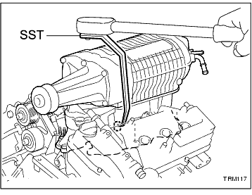
(a) Unclip and move the adjacent wire harnesses to one side as required.
-
(b) Disconnect the fuel injector wire connectors.
-
(c) Using SSTs, uniformly loosen and remove the 6 bolts and 4 nuts.
SST
SR-1143
SR-1145
-
(d) Remove the supercharger and intake manifold assembly and 2 gaskets.
NOTICE:
• Place the supercharger and intake manifold assembly in a jig or on several pieces of wood on a work bench.
• Cover the cylinder head inlet ports to prevent dirt from entering.
-
DISASSEMBLY
1. REMOVE BY-PASS ACTUATOR
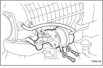
(a) Disconnect the vacuum hose.
-
(b) Loosen the stop bolt lock nut and adjust the stop bolt to provide access to the upper mounting screw.
-
(c) Remove the 2 screws and washers and remove the by-pass actuator.
-
2. REMOVE FUEL DELIVERY PIPE ASSEMBLY (
Click Here
)
3. REMOVE SUPERCHARGER
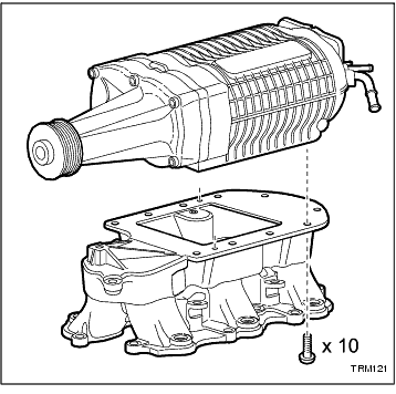
(a) Remove the 10 bolts and supercharger.
-
INSPECTION
1. INSPECT BY-PASS ACTUATOR
(a) Connect a vacuum pump to the by-pass actuator.
-
(c) Apply vacuum for 1 minute. The actuator should continue to remain open.
If the result is not as specified, replace the actuator assembly.
-
REASSEMBLY
1. INSTALL SUPERCHARGER
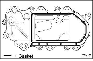
(a) Clean the supercharger and intake manifold mating surfaces.
-
(b) Apply gasket compound to the supercharger surface.
Gasket Compound:
Loctite #518 or equivalent
-
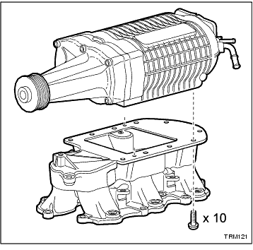
(c) Install the supercharger on the intake manifold, aligning the 2 locating lugs.
-
(d) Apply threadlock adhesive to the 10 bolts.
Adhesive:
Loctite 243 or equivalent
-
(e) Install and tighten the 10 bolts.
Torque:
21 N*m
(214 kgf*cm,
15 ft.*lbf)
-
2. INSTALL FUEL DELIVERY PIPE ASSEMBLY (
Click Here
)
3. INSTALL BY-PASS ACTUATOR
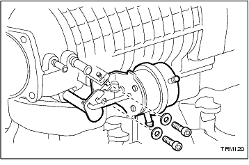
(a) Temporarily install the by-pass actuator with the 2 screws and washers.
-
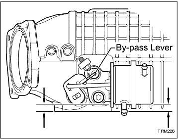
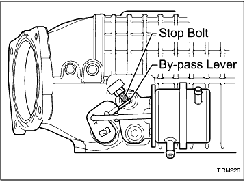
(b) Adjust the by-pass actuator.
(1) Position the actuator parallel with the base of the supercharger and with the by-pass lever in the fully closed position.
(2) Tighten the actuator screws.
Torque:
24 N*m
(244 kgf*cm,
18 ft.*lbf)
(3) Adjust the stop bolt until it touches the by-pass lever.
(4) Turn the bolt one turn further.
(5) Tighten the lock nut securely.
(6) Check by-pass valve operation by moving the lever by hand. Ensure the action is smooth and it does not bind.
-
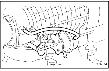
(c) Connect the vacuum hose.
-
INSTALLATION
1. INSTALL SUPERCHARGER AND INTAKE MANIFOLD ASSEMBLY
(a) Clean the intake manifold and cylinder head mating surfaces.
-
(b) Install a new gasket on each cylinder head.
NOTICE:
• Align the port holes of the gasket and cylinder head
• Ensure the gasket is installed in the correct direction.
-
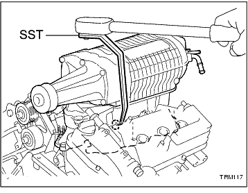
(c) Install the supercharger and intake manifold assembly on the cylinder heads.
-
(d) Using SST, install and uniformly tighten the 6 bolts and 4 nuts in several steps.
HINT:
Use a magnetic screwdriver or similar to assist locating the bolts and nuts.
Torque:
21 N*m
(214 kgf*cm,
15 ft.*lbf)
SST
SR-1143
SR-1145
-
(e) Connect the fuel injector wire connectors.
-
(f) Reposition and clip the adjacent wire harnesses as required.
-
2. CONNECT FUEL TUBE SUB-ASSEMBLY
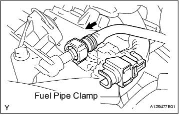
(a) Push the tube connector on to the pipe until the tube connector makes a click sound.
NOTICE:
• Before connecting the tube, ensure it is not damaged. Ensure no dirt present on the connecting surfaces.
• After connecting, check if the fuel tube connector and the pipe are securely connected by pulling on them.
-
(b) Install the No. 2 fuel pipe clamp.
-
3. INSTALL THROTTLE BODY
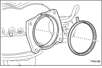
(a) Install a new throttle body gasket.
-
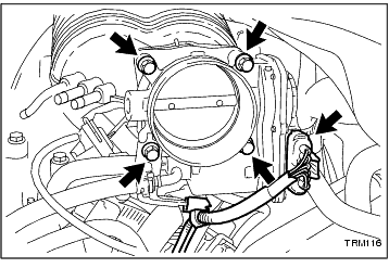
(b) Install the throttle body with the 4 bolts.
Torque:
10 N*m
(102 kgf*cm,
7 ft.*lbf)
-
(c) Connect the wire connector.
-
4. CONNECT VACUUM HOSES
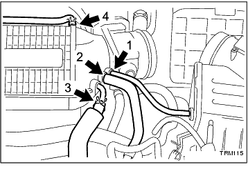
(a) Connect the air cleaner cap vacuum hose (1).
-
(b) Connect the vacuum switching valve hose (2).
-
(c) Connect the ventilation valve hose (3).
-
(d) Connect the brake booster vacuum hose (4).
-
5. INSTALL NO. 2 ENGINE MOUNTING BRACKET
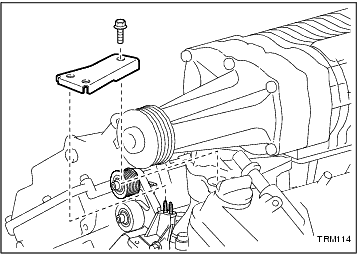
(a) Install the No. 2 engine mounting bracket with the bolt.
Torque:
21 N*m
(214 kgf*cm,
15 ft.*lbf)
-
6. INSTALL DRIVE SUPPORT BRACKET
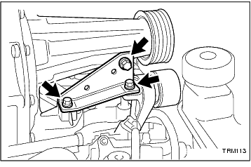
(a) Install the drive support bracket with the 3 bolts.
Torque:
21 N*m
(214 kgf*cm,
15 ft.*lbf)
-
7. INSTALL AIR FILTER HOSE
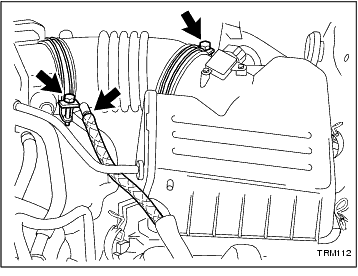
(a) Connect the air filter hose and tighten the hose bands.
-
(b) Connect the ventilation hoses.
-
8. INSTALL V-RIBBED BELT (
Click Here
)
9. INSTALL ENGINE MOVING CONTROL ROD SUB-ASSEMBLY (
Click Here
)
10. INSTALL ENGINE MOUNTING STAY (
Click Here
)
11. INSTALL FRONT FENDER APRON SEAL RH
12. CONNECT CABLE TO BATTERY NEGATIVE TERMINAL
13. INSPECT ENGINE IDLE SPEED (
Click Here
)
14. INSTALL V-BANK COVER SUB-ASSEMBLY (
Click Here
)
15. INSTALL COOL AIR INTAKE DUCT SEAL (
Click Here
)