2AR-FE INTAKE / EXHAUST INTAKE MANIFOLD REMOVAL
PROCEDURE

 1. PRECAUTION
- NOTICE:
-
After turning the ignition switch off, waiting time may be required before disconnecting the cable from the negative (-) battery terminal. Therefore, make sure to read the disconnecting the cable from the negative (-) battery terminal notices before proceeding with work.
-
Click hereGeneral>INTRODUCTION>REPAIR INSTRUCTION>PRECAUTION
2. DISCHARGE FUEL SYSTEM PRESSURE
3.DISCONNECT CABLE FROM NEGATIVE BATTERY TERMINAL
- NOTICE:
-
When disconnecting the cable, some systems need to be initialized after the cable is reconnected.
-
Click hereGeneral>INTRODUCTION>REPAIR INSTRUCTION>INITIALIZATION
4.REMOVE WINDSHIELD WIPER MOTOR AND LINK ASSEMBLY
55702A
5.REMOVE FRONT OUTER COWL TOP PANEL SUB-ASSEMBLY (for LHD)
55702A
6.REMOVE FRONT OUTER COWL TOP PANEL SUB-ASSEMBLY (for RHD)
22030
7.REMOVE THROTTLE WITH MOTOR BODY ASSEMBLY
17650
8.REMOVE VACUUM SWITCHING VALVE ASSEMBLY (for ACIS)
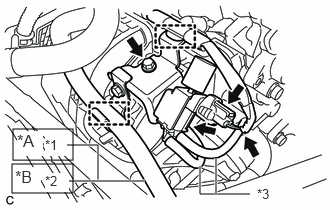
| *A | for LHD |
| *B | for RHD |
| *1 | Union To Vacuum Tube Hose |
| *2 | Union To Check Valve Hose |
| *3 | Vacuum Hose |
for LHD:
Disconnect the union to vacuum tube hose from the vacuum hose clamp.
for RHD:
Disconnect the union to check valve hose from the vacuum hose clamp.
Disengage the wire harness clamp.
Disconnect the 2 vacuum hoses.
Disconnect the vacuum switching valve assembly (for ACIS) connector.
Remove the bolt and vacuum switching valve assembly (for ACIS) from the intake manifold.
12262
9.DISCONNECT NO. 2 VENTILATION HOSE
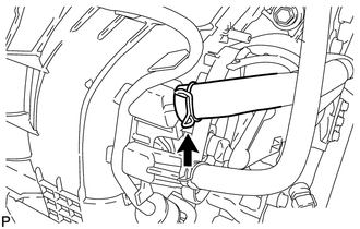
Slide the clip and disconnect the No. 2 ventilation hose from the intake manifold.
44774
10.DISCONNECT UNION TO VACUUM TUBE HOSE (for LHD)
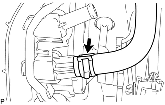
Slide the clip and disconnect the union to vacuum tube hose from the intake manifold.
44773F
11.DISCONNECT UNION TO CHECK VALVE HOSE (for RHD)
Slide the clip and disconnect the union to check valve hose from the intake manifold.
23901
12.DISCONNECT FUEL TUBE SUB-ASSEMBLY
23814B
13.REMOVE FUEL DELIVERY PIPE
17111
14.REMOVE INTAKE MANIFOLD
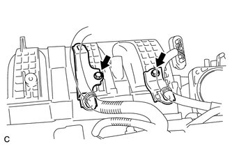
Remove the 2 bolts and 2 wire harness clamp brackets from the intake manifold.
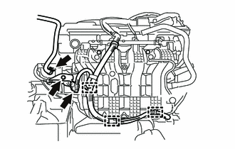
Slide the clip and disconnect the fuel vapor feed hose from the intake manifold.
Disengage the 3 wire harness clamps.
Disconnect the sensor wire connector.
Remove the bolt and wire harness clamp bracket from the intake manifold.
w/ TCV:
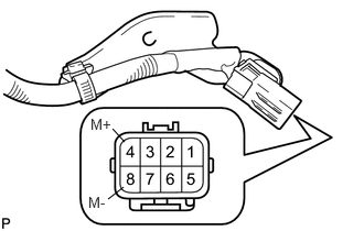
Apply positive (+) battery voltage to terminal 8 (M-) and negative (-) battery voltage to terminal 4 (M+) of the sensor wire connector to close the 4 tumble control valves (TCV).
- NOTICE:
- ·
If this procedure is not performed, the 4 tumble control valves (TCV) may be damaged when the intake manifold is removed.
·Apply battery voltage for 1 to 3 seconds.
·If battery voltage is applied for more than 3 seconds, the intake air control valve actuator (for TCV) may be damaged.
·Do not allow the lead wires to contact the other terminals.
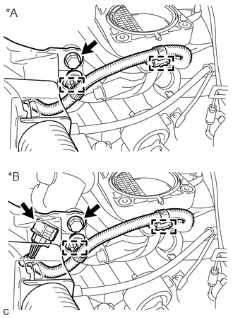
| *A | w/o TCV |
| *B | w/ TCV |
Remove the bolt and disconnect the wire harness.
Disengage the 2 wire harness clamps.
w/ TCV:
Disconnect the intake air control valve actuator (for TCV) connector.
w/o TCV:
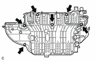
Remove the 6 bolts and intake manifold.
w/ TCV:
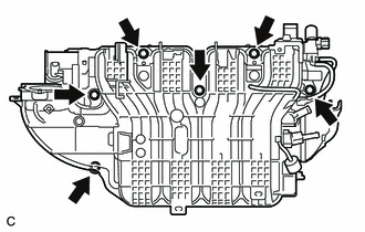
Remove the 6 bolts and intake manifold.
- NOTICE:
-
The 4 tumble control valves (TCV) may be damaged if they are not closed before removing the intake manifold.
- HINT:
-
Connect the battery to the terminals of the intake air control valve actuator (for TCV) to operate the motor and close the 4 tumble control valves (TCV).
-
Click hereEngine / Hybrid System>2AR-FE INTAKE / EXHAUST>INTAKE SYSTEM>ON-VEHICLE INSPECTION
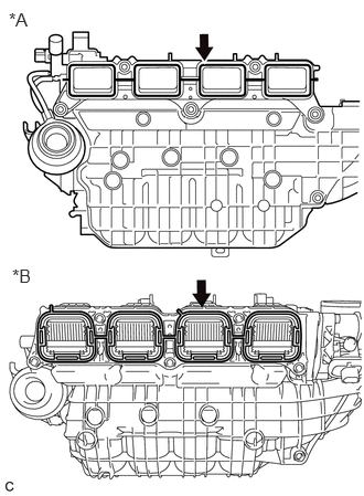
| *A | w/o TCV |
| *B | w/ TCV |
Remove the intake manifold gasket from the intake manifold.
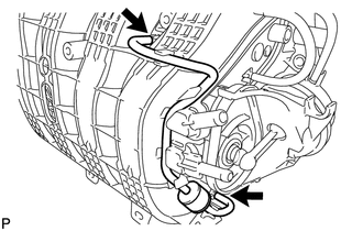
Disconnect the 2 vacuum hoses from the intake manifold and remove the No. 1 check valve.
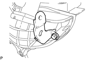
Remove the bolt and wire harness clamp bracket from the intake manifold.